The Box
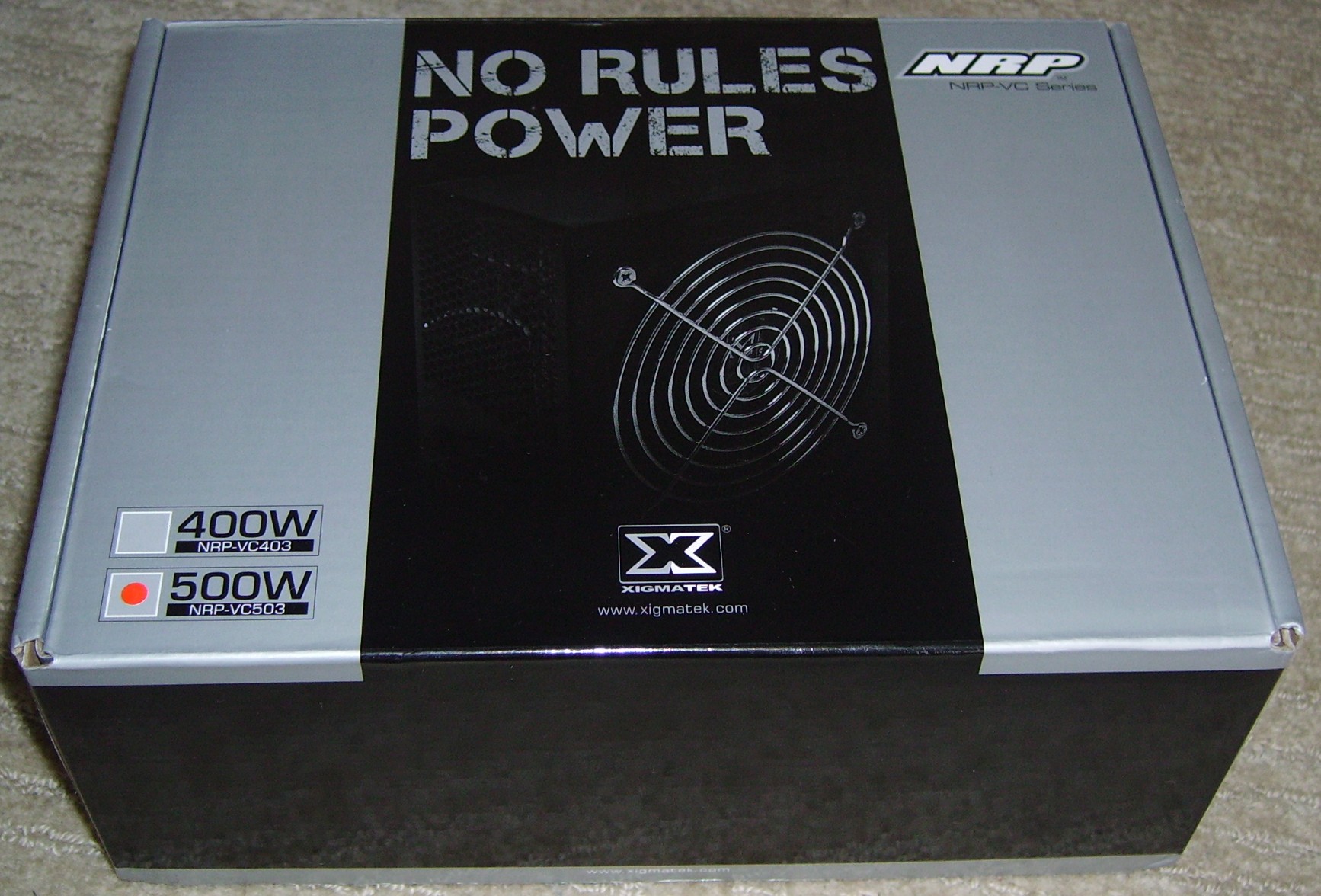
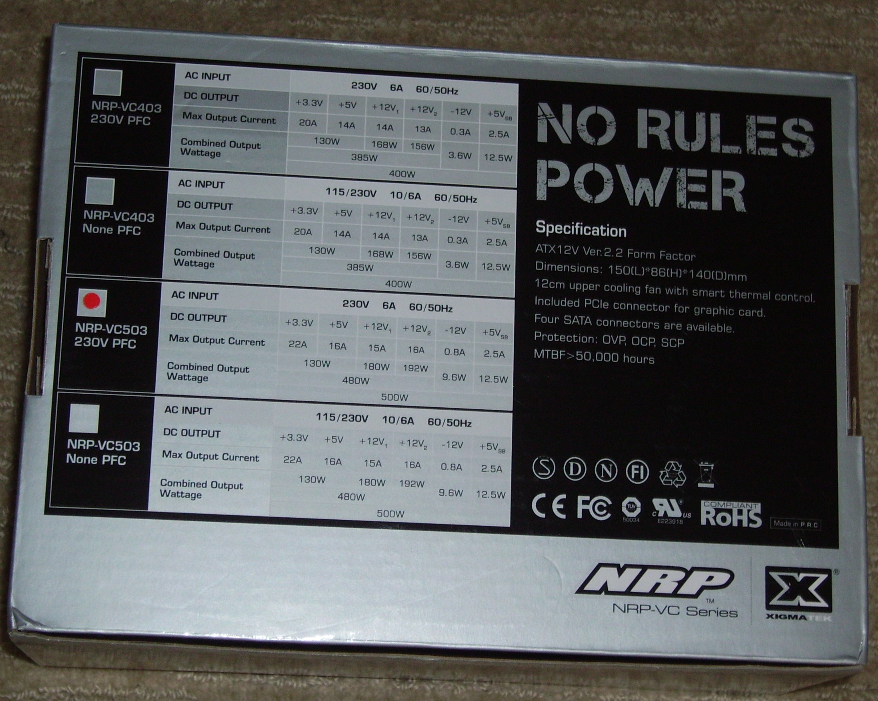
I don’t know about you, but I already have a bad feeling about how this is going to go. I mean, No rules? The unit is obviously not going to follow any of the rules in ATX specifications. Well, at least that’s what the top of the box tells us. Flipping the box over, we can see what’s available from each rail and a list of features and certifications. Our list of features goes:
- ATX12V Ver.2.2 Form Factor
- Dimensions: 150(L)*86(H)*140(D)mm
- 12cm upper cooling fan with smart thermal control
- Included PCIe connector for graphic card
- Four SATA connectors are available
- Protection: OVP, OCP, SCP (No OPP?)
- MTBF>50,000 hours
The box also includes the UL number (E223918), which translates to a Solytech (aka. Deer) build. Solytech can build some good units, but they have also built some very bad ones too. This unit can be had for around $60 AUD if you shop around, which suggests that it will be somewhere in between.
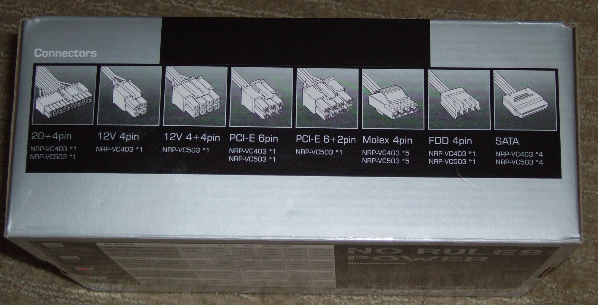
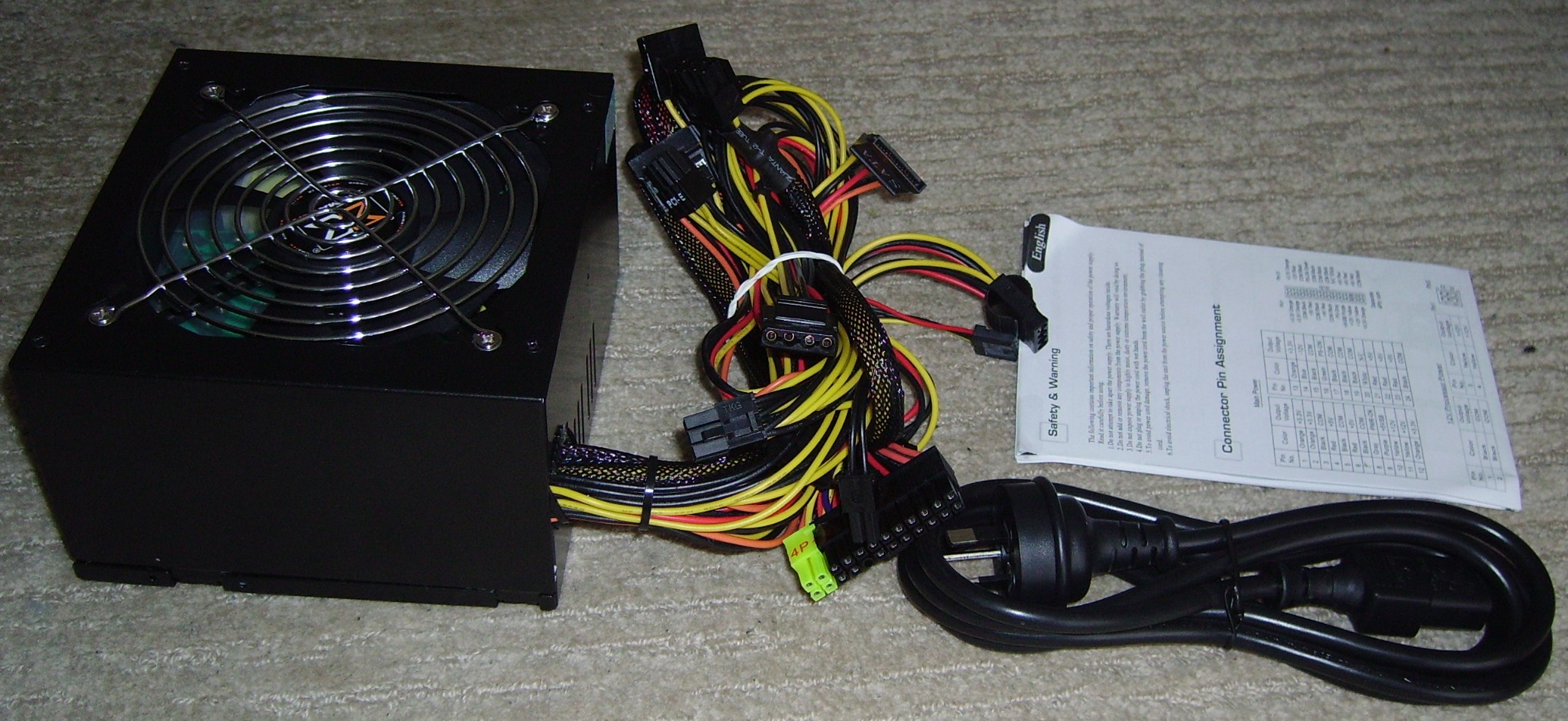
On the back of the box, we can see that this unit has a 20+4 pin ATX connector, an EPS12V connector, a 6 pin PCIe Connector, a 6+2 pin PCIe Connector, 5 peripheral connectors, a floppy connector and 4 SATA connectors. Such a cable configuration is OK for an entry level 500W product. The sides of the box don’t tell us anything interesting. Opening the box up, we have the power supply, a power cable and the manual.
The Power Supply
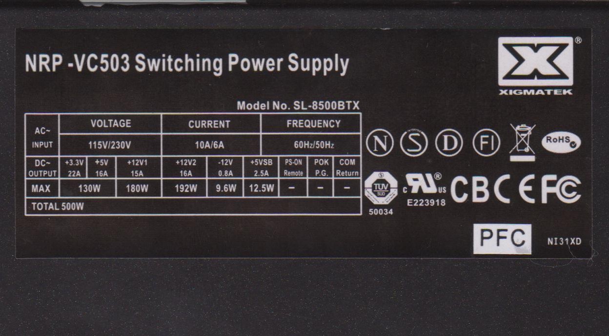
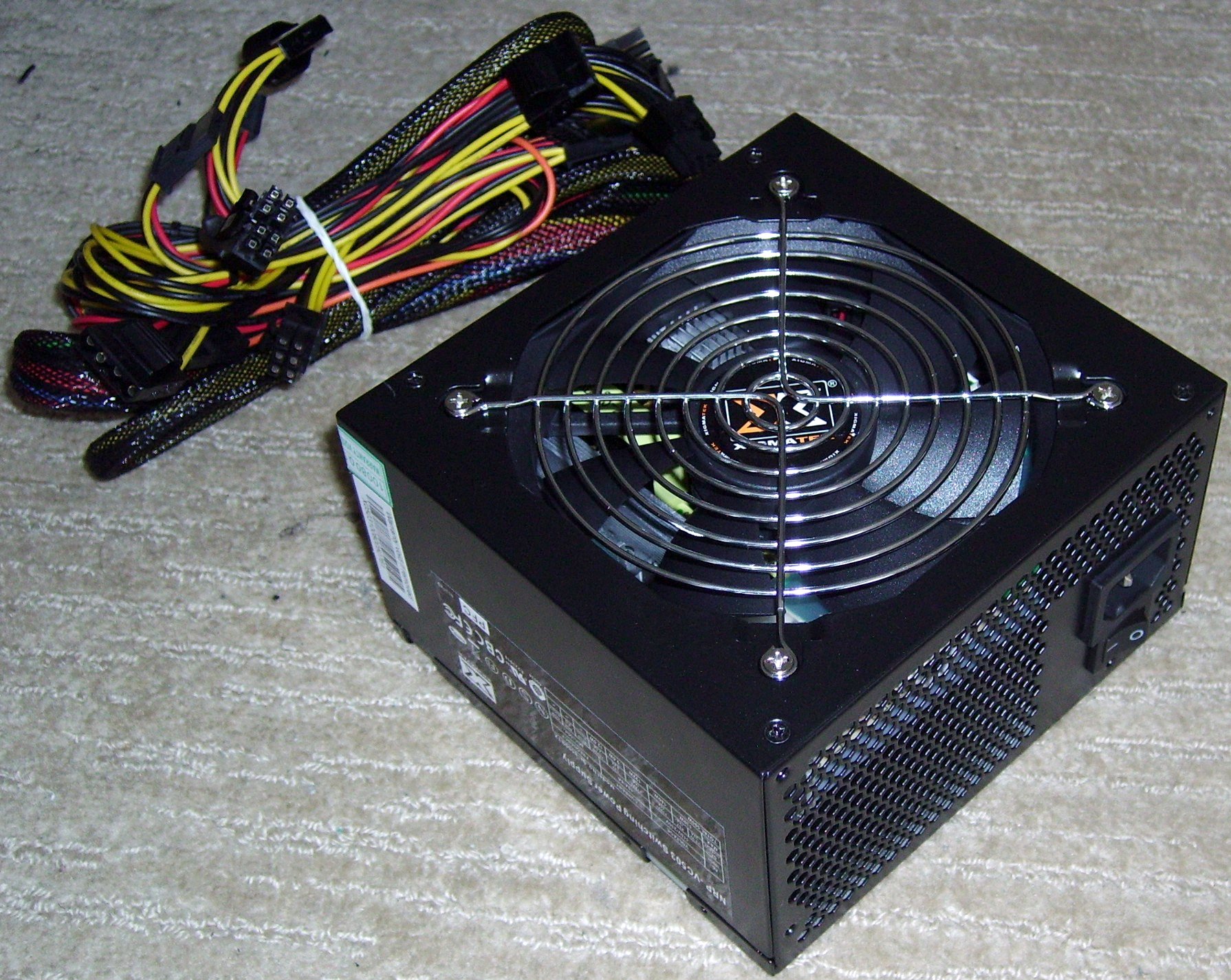
The unit itself is a black, semi-gloss colour, with a fairly boring, black and white label (which we’ll get to in a moment). Although there is very little mention of it on the box, the unit does in fact have PFC. There is a large passive PFC inductor visible through the rear vent. Another feature worth mentioning is the squeezable releases on the peripheral connectors, which makes it easier to remove them from devices that don’t like letting go.
There’s really not much to say about the label. There’s no fancy colours and it doesn’t tell us anything which the box hasn’t already told us, so let’s move on to the load testing.
Load Testing
Test 1 (118.67W Load – Cold)
| Rail | Load | Voltage | Ripple |
| 12v1 | 2.42A | 12.12V | 25mV |
| 12v2 | 2.43A | 12.16V | 28.1mV |
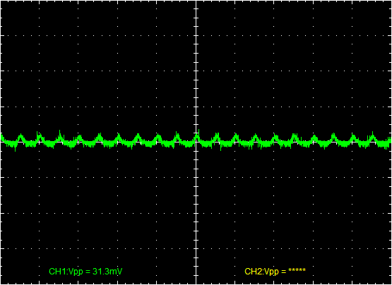
| 5v | 5.13A | 5.13V | 31.3mV |
| 3.3v | 10.06A | 3.32V | 42.2mV |
| −12v | 0A | −11.9V | 25mV |
| 5vsb | 0A | 5.06V | 26.6mV |
| AC Power | 146.05W | ||
| Efficiency | 81.25% | ||
| Power Factor | 0.71 | ||
Test 2 (208.26W Load – Cold)
| Rail | Load | Voltage | Ripple |
| 12v1 | 4.84A | 12.10V | 26.6mV |
| 12v2 | 4.85A | 12.13V | 23.4mV |
| 5v | 10.16A | 5.08V | 31.3mV |
| 3.3v | 10A | 3.30V | 39.1mV |
| −12v | 0.1A | −12.02V | 18.1mV |
| 5vsb | 1A | 5.01V | 15.6mV |
| AC Power | 254.7W | ||
| Efficiency | 81.77% | ||
| Power Factor | 0.75 | ||
Test 3 (265.74W Load – Cold)
| Rail | Load | Voltage | Ripple |
| 12v1 | 7.23A | 12.05V | 46.9mV |
| 12v2 | 7.23A | 12.05V | 40.6mV |
| 5v | 10.22A | 5.11V | 40.6mV |
| 3.3v | 10A | 3.3V | 60.9mV |
| −12v | 0.1A | −12.26V | 37.5mV |
| 5vsb | 1A | 5.01V | 35.9mV |
| AC Power | 327.23W | ||
| Efficiency | 81.21% | ||
| Power Factor | 0.75 | ||
Test 4 (323.17W load – Cold)
| Rail | Load | Voltage | Ripple |
| 12v1 | 9.6A | 12.00V | 34.4mV |
| 12v2 | 9.59A | 11.99V | 39.1mV |
| 5v | 10.32A | 5.16V | 35.9mV |
| 3.3v | 10.06A | 3.32V | 48.4mV |
| −12v | 0.1A | −12.46V | 45.3mV |
| 5vsb | 1A | 5.01V | 25.0mV |
| AC Power | 392.7W | ||
| Efficiency | 82.30% | ||
| Power Factor | 0.75 | ||
Test 5 (350.65W Load – Cold)
| Rail | Load | Voltage | Ripple |
| 12v1 | 9.58A | 11.97V | 46.9mV |
| 12v2 | 11.95A | 11.95V | 46.9mV |
| 5v | 10.34A | 5.17V | 35.9mV |
| 3.3v | 10.06A | 3.32V | 57.8mV |
| −12v | 0.11A | −12.7V | 48.4mV |
| 5vsb | 0.1A | 5.01V | 32.8mV |
| AC Power | 435.9W | ||
| Efficiency | 80.44% | ||
| Power Factor | 0.75 | ||
Test 6 (401.48W Load – Hot)
| Rail | Load | Voltage | Ripple |
| 12v1 | 12.01A | 12.01V | 51.6mV |
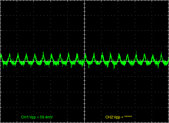
| 12v2 | 12.02A | 12.02V | 59.4mV |
| 5v | 14.79A | 4.93V | 31.1mV |
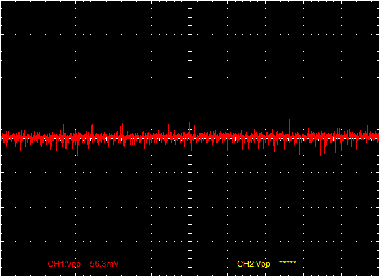
| 3.3v | 10.06A | 3.32V | 56.3mV |
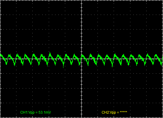
| −12v | 0.11A | −13.06V | 53.1mV |
| 5vsb | 1A | 5.01V | 37.5mV |
| AC Power | 523.3W | ||
| Efficiency | 76.72% | ||
| Power Factor | 0.74 | ||
Test 7 (453.85W Load – Hot)
| Rail | Load | Voltage | Ripple |
| 12v1 | 14.3A | 11.92V | ? |
| 12v2 | 14.34A | 11.95V | ? |
| 5v | 14.73A | 4.91V | ? |
| 3.3v | 10.03A | 3.31V | ? |
| −12v | 0.11A | −13.21V | ? |
| 5vsb | 1A | 5.00V | ? |
| AC Power | 619.4W | ||
| Efficiency | 73.27% | ||
| Power Factor | 0.74 | ||
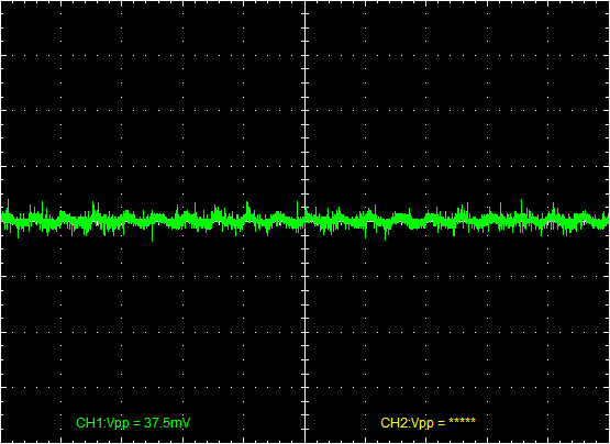
Oh ‘deer’ me. This unit really did break some rules, but lets start with the good news. The voltage regulation was great. No voltages ever came close to going out of spec. The worst performer, as usual, was the −12v rail, although part of the problem is that the load tester currently only allows for 0.1A of load on that rail. The acoustic noise was also very good. It was inaudible throughout the testing. The efficiency was OK. Not great, but just OK. It was above 80% until test 6, where it dropped considerably to 76.72%, indicating that the unit was reaching its limits. It dropped a further 3.45% during test 7. The passive PFC was able to keep the power factor above 0.7 the whole time, which is typical for units with passive PFC, although still no match for active PFC. The ripple, however was a cause for concern. Once we got to Test 3, it was out of spec on the 3.3v rail at 60.9mV. It went down somewhat on subsequent tests, but was still too high. Then we got to Test 7 and things only got worse. As soon as I finished recording the voltages and AC power draw, the unit exploded. Unfortunately, I didn’t get to read the ripple, which is why the question marks in the table for test 7.
| Rail | Test 6 (401.48W) | Test 7 (453.85W) |
| 12v1 | 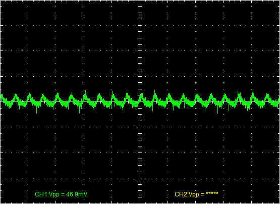 |
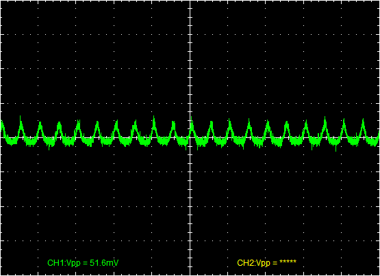 |
| 12v2 | 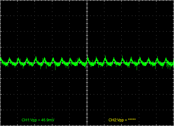 |
 |
| 5v | 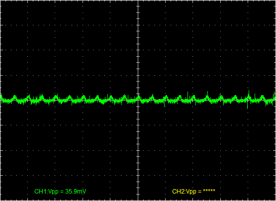 |
 |
| 3.3v | 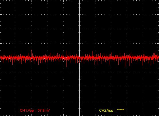 |
 |
| −12v | 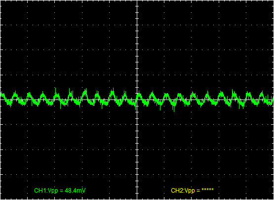 |
 |
| 5vsb | 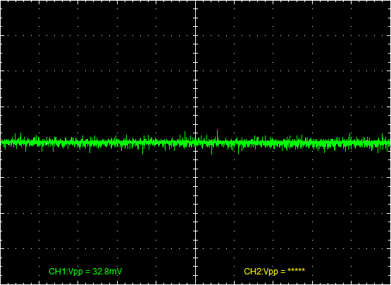 |
 |
The Explosion
Below, you can see a video of the explosion. It happens about 14 seconds into the video.
A Look Inside
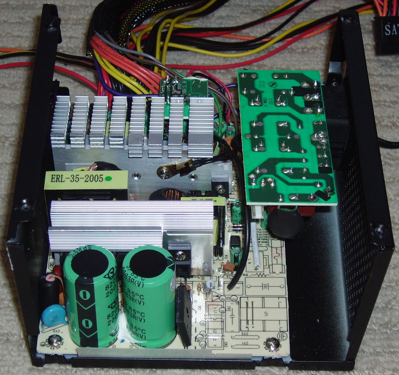
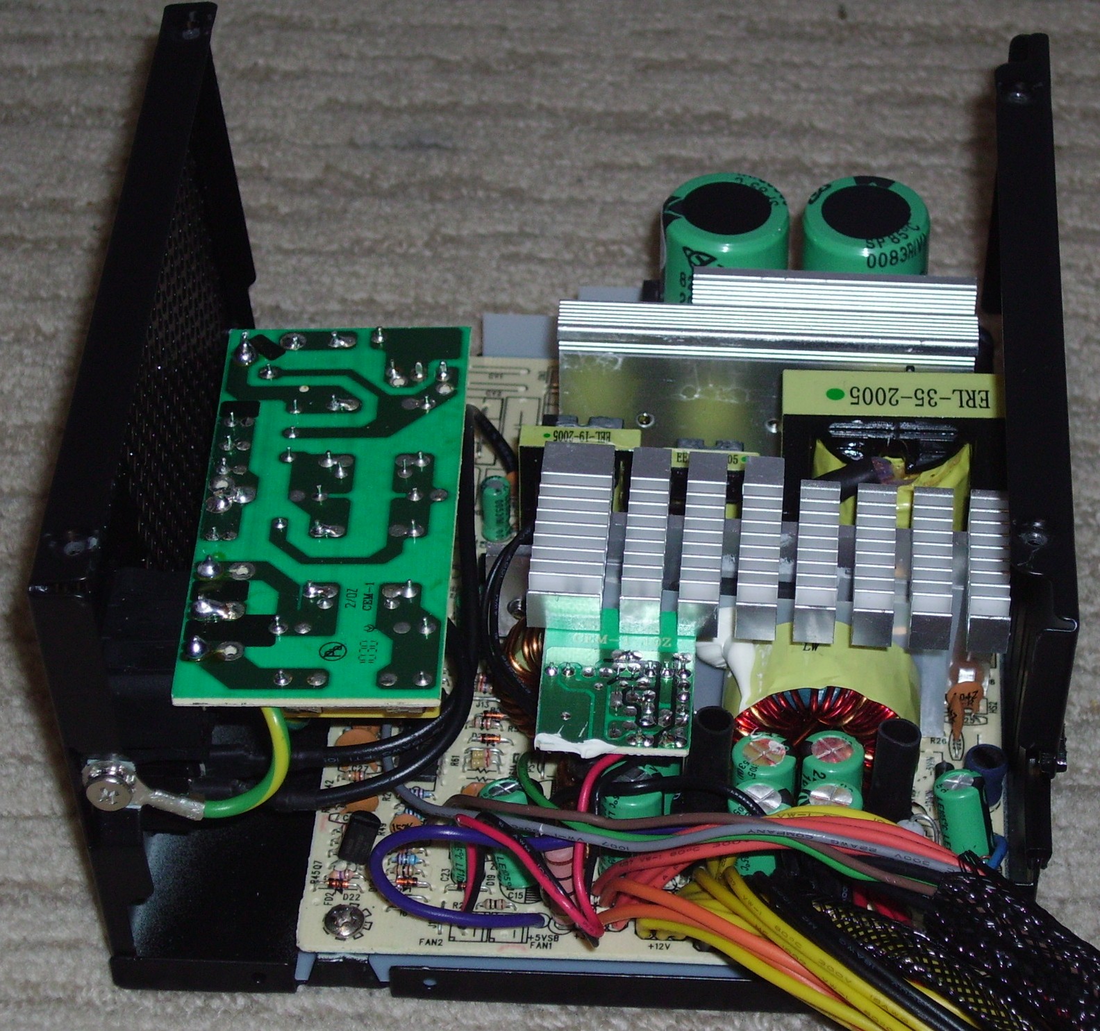
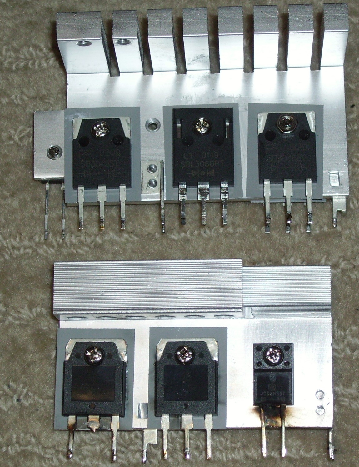
I know what you’re all thinking: “What on earth happened to the input filtering?” That’s on a separate PCB attached to the AC receptacle because the large PFC inductor prevents that part of the PCB from being used. It contains two X caps, two common-mode chokes, four Y caps and an NTC thermistor. There are also two MOVs present on the main PCB, hidden between the 820μF Yang Chun primary capacitors and the primary heat sink, plus another Y capacitor after the rectifier. Screwed on to the primary heat sink are two Advanced Technology Electronics D209L transistors (one of which looks rather charred now) rated for 12A at 25°C, although the data sheet doesn’t say what the ratings are at higher temperatures.
On the secondary heat sink, the unit uses a PanJIT SB3045ST Schottky rectifier on the 3.3v rail, a Lite-on SBL3060PT Schottky rectifier on the 12v rail and two more SB3045ST rectifiers on the 5v rail. This means that the unit has twice as much current available on the 5v rail as on the 12v, so it’s more suited to an older PC. Unlike the label and box suggest, the unit only has a single 12v rail. There is only one group of 12v wires and no OCP (unlike what the box says). All of the capacitors in this unit are Chinese, from Yang Chun, another possible cause for concern.
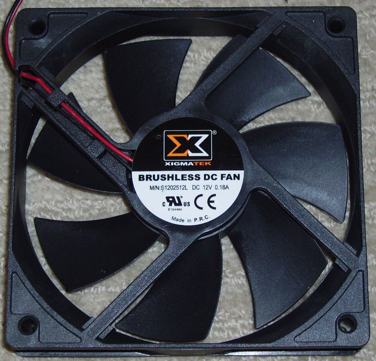
The fan is branded Xigmatek like the PSU, but the UL number (E154464) points to one of Solytech’s favourite fan brands, Globe Fan. I’m not too concerned about this. Globe fans are usually reliable. Rather than the usual birds eye view of the internals, I’ve included a picture of the heat sinks to the right of the fan. Note the burn marks and melted legs on the two outer transistors on the primary (bottom) heat sink. Closer inspection revealed that the middle transistor was also burned and cracked, indicating that all three failed almost simultaneously.
Specifications
| Real Wattage | 400W |
| OEM | Solytech |
| PFC | Passive |
| Price | $60 (AUD) |
| ATX Connector type | 20+4 pin |
| CPU Connector | EPS12V (4+4 pin) |
| PCIe Connectors | 1× 6 pin, 1× 6+2 pin |
| Molex (Peripheral) Connectors | 5 |
| FDD Power connectors | 1 |
| SATA Power connectors | 4 |
Conclusions
Pros: Good voltage regulation, quiet, squeezable releases on peripheral connectors, input filtering
Cons: Can’t deliver 500W, Low quality capacitors, Ripple on 3.3v rail too high
Bottom Line: It won’t get the fail award, but it’s not a recommended product.
Score: 5/10
Discuss this review in our forums here!
Review sample source: Lower Clarence Computers
