Contents
- 1Introduction
- 1.1Packaging and accessories
- 2Connectors & cabling
- 2.1Casing & cooling
- 3Input filtering
- 4Primary side
- 4.1+5 V stand-by rail
- 5Secondary side
- 5.1Build quality
- 6Load testing
- 6.1Loading +5 V SB
- 6.2Voltage hold-up time
- 6.3Combined loading
- 6.4Combined loading ripple
- 6.5Crossloading, overloading
- 6.6Crossloading, overloading ripple
- 6.7Fan speed and temperatures
- 7Conclusion and evaluation
- 7.1Thanks
- 7.2Discussion
Secondary side
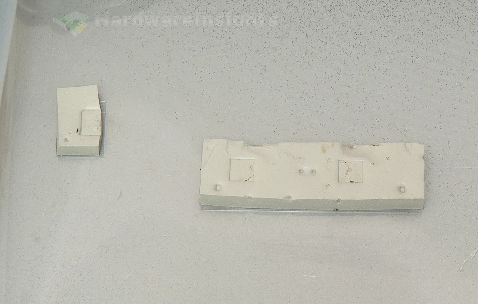
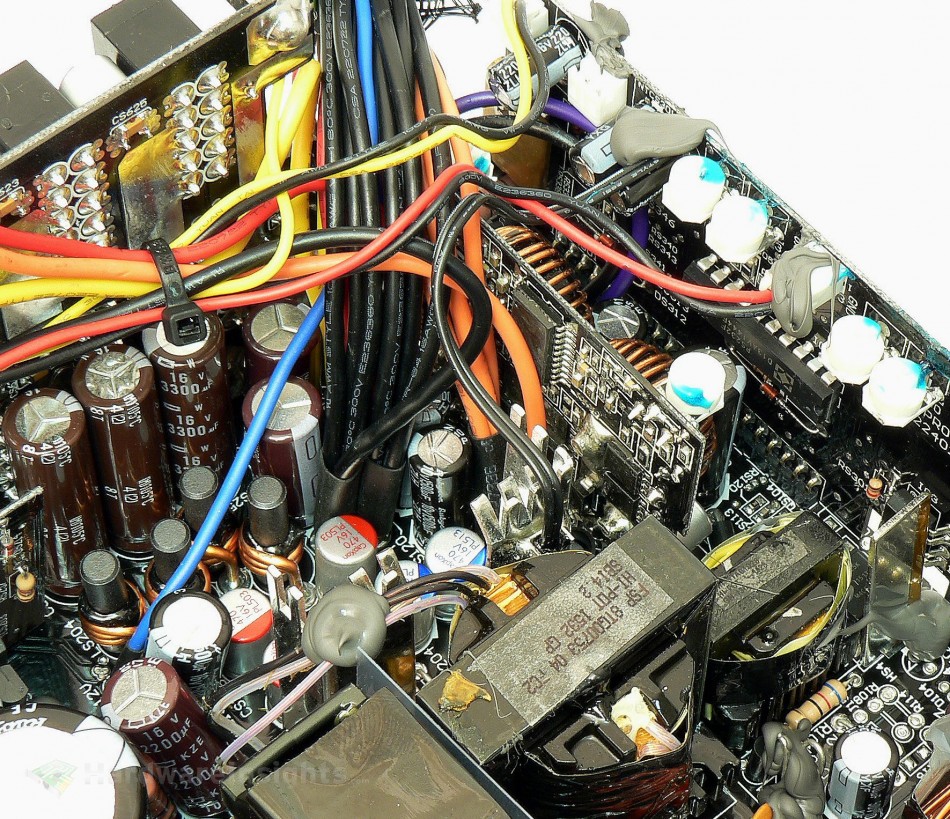
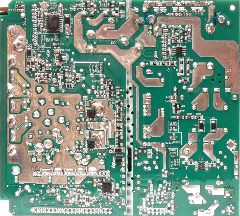
There are two pairs of Toshiba TPHR8504PL (150/500 A at 40 V and 25 °C, Rds(On) 1.4 mΩ at 50 A and Vgs of 4.5 V, 0.85 mΩ at 10 V) transistors in a modern “SOP Advanced” package (also known as HSON or DFN5x6-8 – the package name varies by manufacturer) used for +12V rectification. They are located on the solder side of the board and there is also an extra unpopulated area for two more transistors (for the higher-power versions of this unit). Both are cooled by two copper heatsinks soldered though the board with copious amounts of solder and also by direct contact with the units casing via heat-conducting silicone pads. Six CapXon 470/16 polymer capacitors are used for the filtering in front of the Pi coils and three Nippon Chemi-Con “W” (custom series) 3300/16 capacitors along with two KZE 2200/16 for the pi filter output. There are indeed four output rails plus an exclusively internal fifth which provides power for the DC-DC converters. The custom series 3300/16 capacitors are most likely quite similar to my own custom-order KZN 3300/16, but I’m not absolutely certain, as I can’t verify precisely which Chemi-Con series these are based on.
There are six more polymers on the board carrying both converters, two 330/16 provide additional input filtering and two 560/6.3 per rail that provide output filtering with an extra Rubycon ZLH 1500/10 per rail. Our beloved Anpec APW7159C acts as the controller of the two pairs of transistors. Unfortunatelly I am unable to identify the transistors themselves, as they’re covered with a layer of lacquer. The APW7159 has proven it can deliver a very precise output, as we’ve recently observed with the Corsair RM550x, so I’m looking forward to the results here. As has been previously noted, the main driver chip is located on the secondary side, on a daughterboard near the input capacitors. It uses a Silicon Labs SI8233BD which is a dual-isolated driver that controls the switching transistors, with the chip being situated on the daughterboard’s solder side. Another Rubycon ZLH 100/16 is used in this circuitry as well.
FSP Group once again used the PS232 secondary monitor. I recently noticed that Gabriel over at Hardware Secrets has been able to get this datasheet. It is a 6-channel Silicon Touch Technology PS232S monitor chip, and it’s capable of monitoring all of the four +12V rails. As is usually the case with monitoring chips, it also provides the Power Good signal and accepts the PWR On signal from the motherboard. Also located on this board is the D45H11 (-10 A at -80 V and 25 °C) PNP transistor. It basically acts as a linear regulator so that the PSU fan (as well fans conected to the four external fan headers) are all regulated to run at the same speed. While it is a nice feature, there are literaly dozens of similar regulators on the market priced at anywhere from $10 and up.
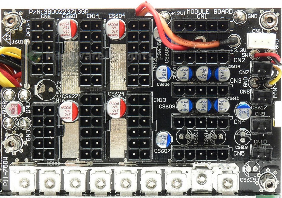
As for the modular board, all the +12V rails and ground connections for the EPS and PCIe connectors are both screwed on and soldered on the modular board, while they’re only soldered to the mainboard. The five modular peripheral connectors share the common rail with the other connectors, but separate 16AWG wires are used for the connection between this circuit on the modular board and the mainboard. The +3.3 and +5 V rails are connected by both 16AWG and 18AWG wires. There are four extra CapXon 270/16 and three 100/16 polymers for the EPS/PCIe filtering, plus three more for the peripheral connectors, all for the +12 V rails. Then there are two for +3.3/+5 V rails, one (Enesol Enecap) for the stand-by rail, and one CapXon for the fans.
Build quality
As usual, I’ll focus on the overall build quality and other things like electrical safety here, as the quality of the components that were used was already discussed before. The seperation between the primary and secondary sides is adequate, and we also have some extra holes that were drilled under all the transformers and between the capacitors. The varistor is not insulated which isn’t really acceptable for a unit of this price, but otherwise the overall insulation is good. Quite a lot of silicone is used. Wire leads are mostly cut precisely enough or at the very least bent properly. The unit uses a double-sided epoxied fiberglass PCB.
Conductive paths are reinforced by a layer of solder. The soldering itself is not that bad even though there are some manually-re-soldered spots. It’s evident that FSP tried to clean the mainboard, but it seems as though the unintended result was the soldering flux (or maybe some other chemical) only getting smeared all over the entire board. On the bright side, there weren’t really that many solder balls (or other solder residue), and taking into account how complex the manufacturing of this unit is, finding about 6 tiny and 2 medium ones is pretty good. My overall impression is OK, and I think I’ll only deduct 8 points for this unit. We have seen far worse units in terms of quality control in the last year or so…


