Contents
- 1Introduction
- 1.1Packaging and accessories
- 2Connectors & cabling
- 2.1Casing & cooling
- 3Input filtering
- 4Primary side
- 4.1+5 V stand-by rail
- 5Secondary side
- 5.1Build quality
- 6Load testing
- 6.1Loading +5 V SB
- 6.2Voltage hold-up time
- 6.3Combined loading
- 6.4Combined loading ripple
- 6.5Crossloading, overloading
- 6.6Crossloading, overloading ripple
- 7Conclusion and evaluation
- 7.1Thanks
- 7.2Discussion
Primary side
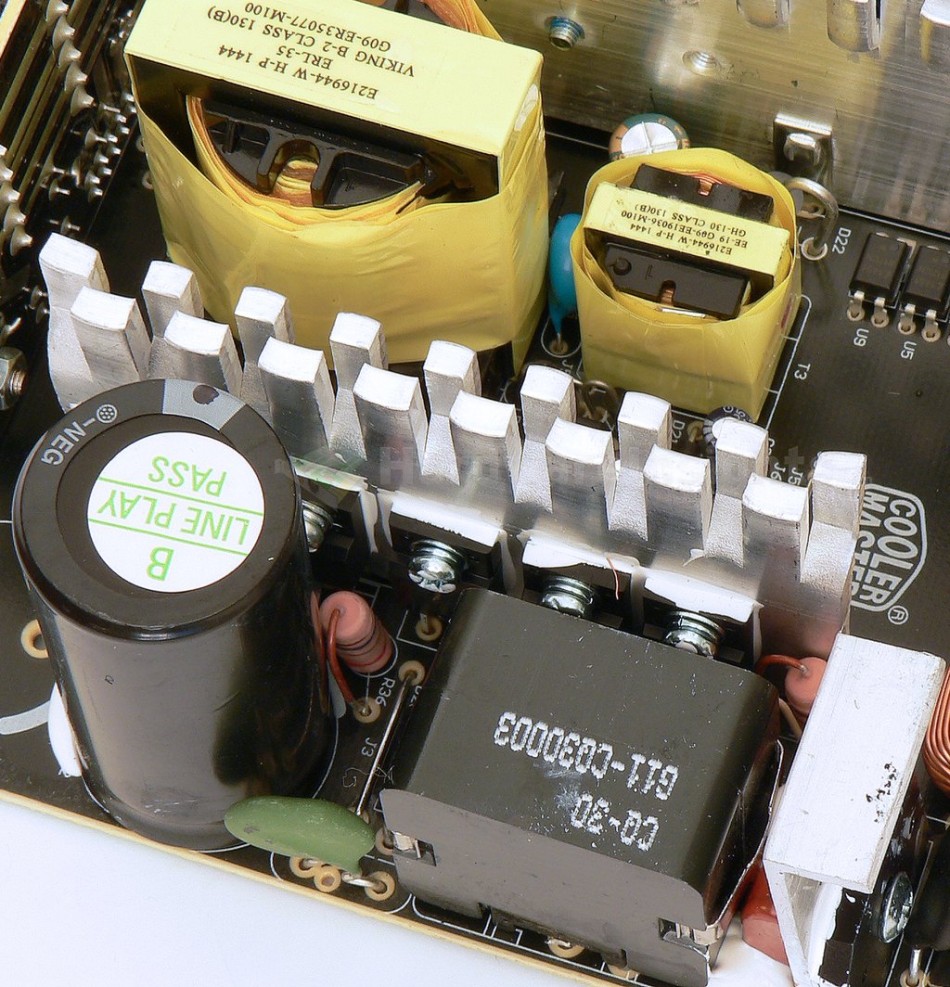
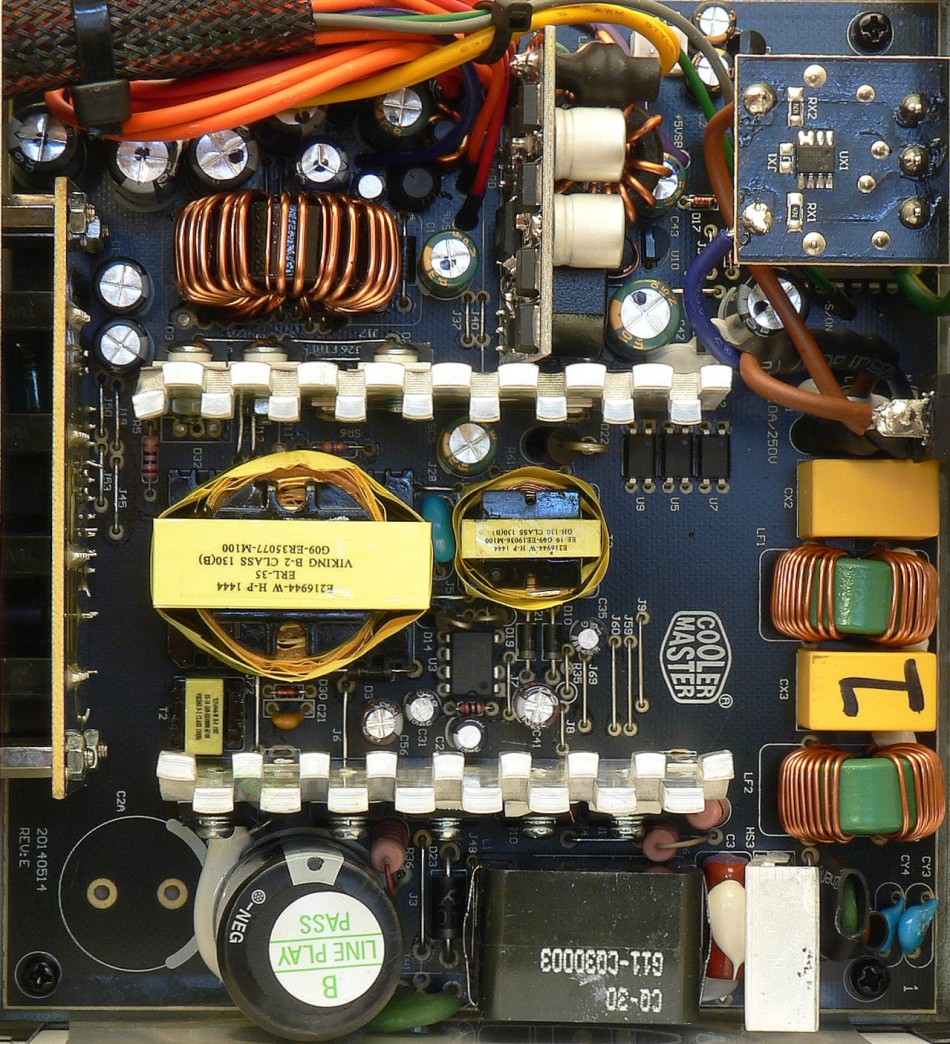
The primary side starts with a GBU1006 bridge rectifier which can handle up to 10 A (continuously) with heatsink at 800 V and 100 °C or 220 A surge (8.3 ms) at 25 °C. The voltage drop is 1.1 V per diode at 10 A. It is mounted on a dedicated heatsink. The PFC coil is basically a transformer type with the windings mostly closed inside the core. Transistors in PFC are two Silan Microelectronics SVF20N50F (20/80 A at 25 °C and 500 V, Rds(On) 270 mΩ at 10 A and 25 °C), mounted on common primary heatsink. There is also the Power Integrations LXA08FP600 (8/350 A at 600 V and 150 °C, drop of 2.94 V at 8 A and 25 °C). Everything in TO-220F package.
The capacitor charged by PFC circuit is CapXon LP 470 μF/400 V for 105 °C (I forgot to measure its actual capacitance) with endurance of 2000 hours. Voltage rating could be higher though, manufacturing quality of C(r)apXon is not very good. The platform is clearly ready for higher power as it has two spots for input capacitors. The PFC circuitry together with primary switching is driven by Champion Micro CM6800TX. All the capacitors around it are a combination of JunFu and Su’scon so one of the worst selections available, I do not think it is necessary to list which exactly. There is also the CM03X to reduce standby power consumption.
Switching transistors are two SigmaChip SGX190N60SJ (20.5/56 A at 25 °C and 600 V, Rds(On) 190 mΩ at 10 A and 25 °C, 0.45 Ω at 150 °C) in ordinary two-transistor forward configuration. Again both in TO-220F package. The ERL-35 transformer is insulated by yellow tape, this is somewhat unusual as CWT usually uses green tape.
+5 V stand-by rail
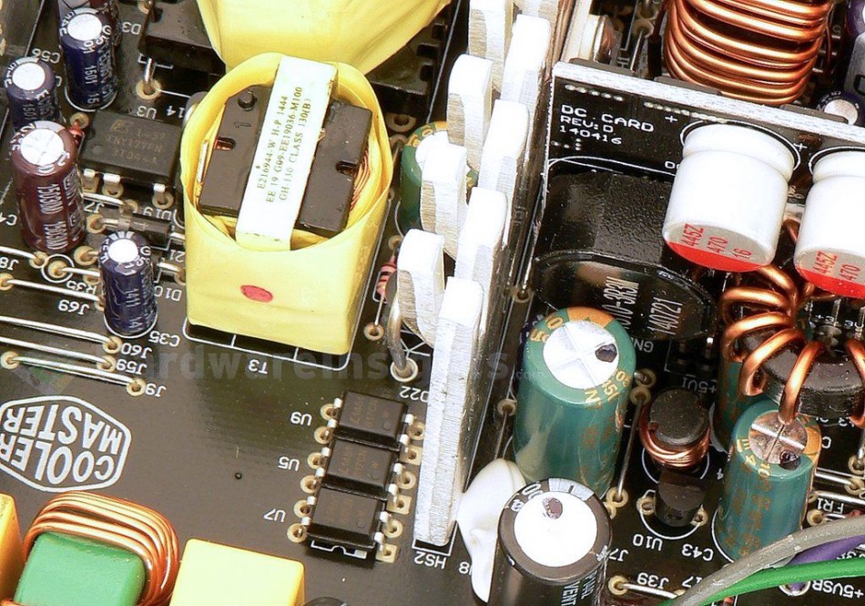
The stand-by rail uses well-known PWM driver with integrated transistor, the Power Integrations TNY177PN. It is specified for maximum power of 18W “open-frame” with full-range input. The supply uses EE-19 transformer.
On the secondary side is just a single Schottky diode in DO package for one-way rectification. Filter consists of two C(r)apXon GF capacitors (2200/10 D10 and 2200/6.3 D8), again one of the worst possible choices.


