Contents
- 1Introduction
- 1.1Packaging and accessories
- 2Connectors & cabling
- 2.1Casing & cooling
- 3Input filtering
- 4Primary side
- 4.1+5 V stand-by rail
- 5Secondary side
- 5.1Build quality
- 6Load testing
- 6.1Loading +5 V SB
- 6.2Voltage hold-up time
- 6.3Combined loading
- 6.4Combined loading ripple
- 6.5Crossloading, overloading
- 6.6Crossloading, overloading ripple
- 7Conclusion and evaluation
- 7.1Thanks
- 7.2Discussion
Primary side
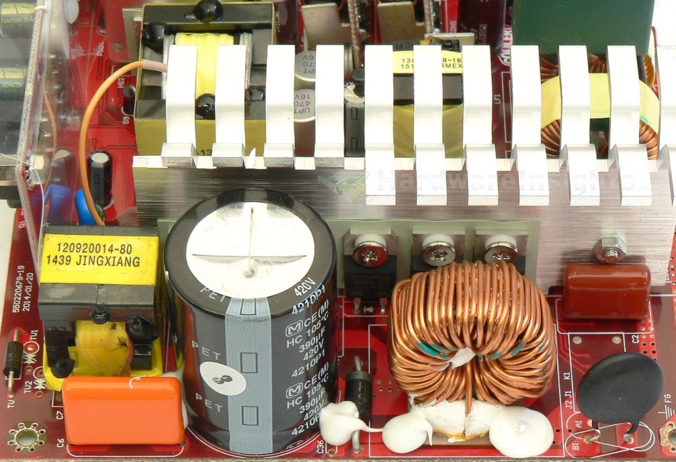
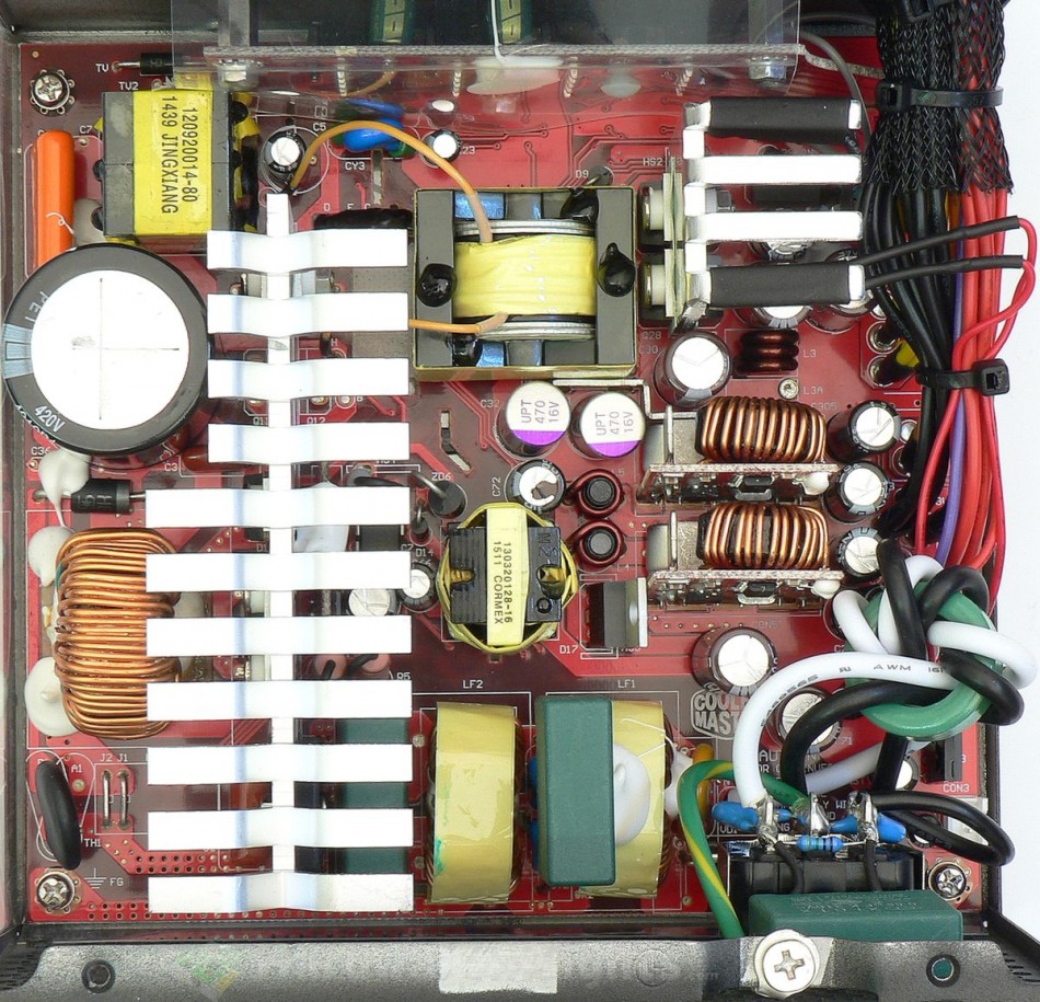
The rest of the unit is much the same just with quality capacitors. We start with GBU15L06 bridge rectifier. It handles 15 A continuous with heatsink at 600 V and 115 °C or 450 A surge (1 ms, 125 °C) with the voltage drop 0.9 V per diode at 7.5 A and 25 °C. The PFC coil is somewhat smaller but has more winding and is quite capable as I have seen back in 2013. Transistors in PFC are two IPP50R280CE (13/42.9 A at 25 °C and 500 V, Rds(On) 280 mΩ at 4.2 A and 25 °C, 660 mΩ at 150 °C), mounted on common primary heatsink together with ST Microelectronics STTH8R06D diode (8/30 A at 600 V and 130 °C, drop of 2.9 V at 8 A and 25 °C). Everything in TO-220 package. There is one piece of aluminium swarf on the heatsink, quite loose, if I would not have removed that, it could have torn off in the future and shorted something inside the unit. Minus point for that.
The capacitor charged by PFC circuit is Panasonic HC 390 μF/420 V for 105 °C (measures 353 μF) with lifetime of 2000 hours. Could be a little bit more but otherwise this cap is OK. The PFC circuitry is driven by Champion Micro CM6500TNX (on a small daughterboard on the other side of the heatsink). Switching transistors are Magnachip MDP18N50 (18/72 A at 25 °C and 500 V, Rds(On) 0.27 Ω at 9 A), one in the front side of the heatsink (between the bulk cap and resonant transformer) and the other on the rear side. They are in the half-bridge configuration. The resonant controller is on secondary side, connected to primary by Silicon Labs Si8230BD isodriver. A Rubycon YXG 100/50 capacitor is used on feedback. Last year I took half a point for not enough overbuilding for my taste. Well, after seeing many other units incl. Seasonic with only 13A switchers, this is still above average.
+5 V stand-by rail
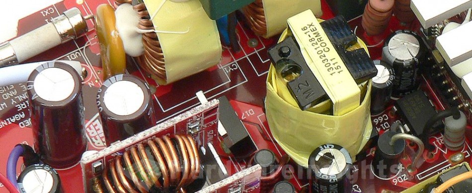
The stand-by rail uses Sanken Electric STR-A6069H PWM controller with integrated transistor for 700 V. It is rated only for 10 W while the unit’s specification says 12.5 W output power so I am curious about the result. Its supply rail is filtered by Rubycon YXF 47/50.
Behind the 18mm transformer is a PFC Device Corporation PFR10V45CT rectifier (10/200 A at 150 °C and 40 V, drop of 0.46 V at 8 A and 25 °C) in TO-220 package. Filter consists of two Nippon Chemi-Con KZE 2200/16 capacitors with no coil. One strange thing though, it seems there is a transistor leading from the +5 V rail to +5 V SB. I am not sure what its purpose is but it probably helps regulating stand-by voltage or maybe even makes the unit draw from +5 V rail to feed +5 V SB output and save a few watts.


