Contents
- 1Introducing the Cooler Master V650
- 1.1Packaging and accessories
- 2Connectors & cabling
- 2.1Casing & cooling
- 3Input filtering
- 4Primary side
- 4.1+5 V stand-by rail
- 5Secondary side
- 5.1Build quality
- 6Load testing
- 6.1Loading +5 V SB
- 6.2Hold-up time
- 6.3Combined loading
- 6.4Combined loading ripple
- 6.5Crossloading, overloading
- 6.6Crossloading, overloading ripple
- 6.7Fan speed, temperatures and noise
- 7Conclusion and evaluation
- 7.1Thanks
- 7.2Discussion
Primary side
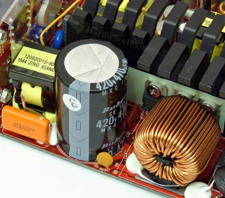
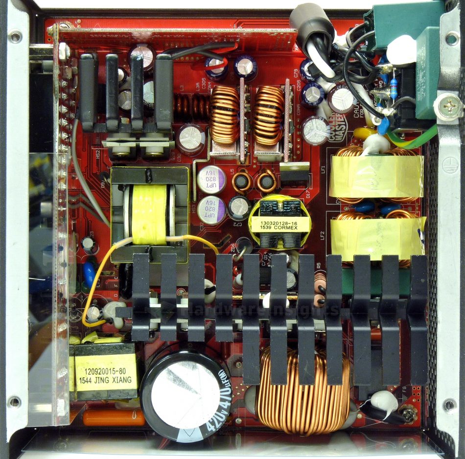
The primary side begins with the input bridge rectifier, the GBU1006 which shares the common primary side heatsink. It can handle 10 A at 100 °C and 800 V continuously, or 220 A peak (for 8.3 ms). Its voltage drop (counting for losses) is 1.1 V per diode at 10 A. There are two N-FETs in the boost-type PFC circuit in parallel, the Magnachip MMP60R190P (20/60 A at 600 V and 25 °C, RDS(On) 190 mΩ at 9.5 A) in a TO-220 package. The diode is the ST Micro STTH12R06D (12 A at 600 V and 125 °C, 100 A peak for 10 ms at 25 °C, drop of 1.8 V at 12 A and 125 °C, 2.9 V at 25 °C) in a TO-220AC package. The PFC coil seems capable enough, it has quite a wide and seemingly thick enough wire. Notice the layer of PCB material as well as some epoxy underneath the coil.
The bulk capacitor that gets charged from the PFC is a Rubycon MXG 470 μF/420 V. I measured its actual capacitance at 419 μF. This series has a minimum lifetime of 3000 hours at its maximum temperature (105 °C) and ripple. I like it. The switching transistors are four Infineon IPP50R280CE (13/42.9 A at 25 °C and 500 V, RDS(On) 0.28 Ω at 4.2 A and 25 °C, 0.66 Ω at 150 °C) in the LLC resonant full-bridge configuration. All the silicon here shares the common primary side heatsink which has a black anodizing layer (unlike in the V550S).
As for the driving circuitry, there is the latest Champion Micro CM6502UHHX PFC controller. A Rubycon YXG 100/50 seems to filter its power supply. The PFC controller shares a small daughterboard together with the CM03X microchip to reduce no (or low) load losses. The tri-way switching/synchronous rectification resonant controller (two PWM modes and FM modulation) is the usual CM6901T6X. As usual, it is physically located on the secondary side. The main transformer is quite small which they accomplish by way of benefit from using a full-bridge configuration.
+5 V stand-by rail
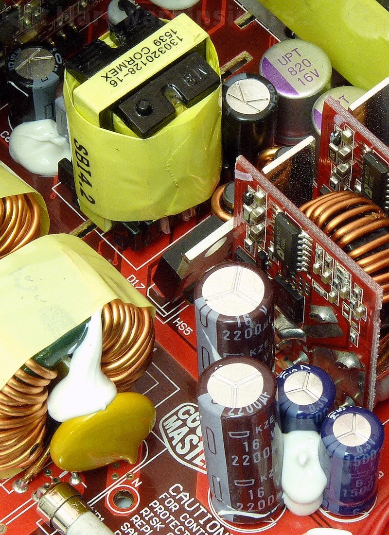
The stand-by rail uses Sanken Electric STR-A6069H PWM controller with integrated transistor for up to 700 V (RDS(On) 6 Ω). It is rated for 10 W plus 20-40 % depending on the configuration. Its supply rail is filtered by a Chemi-Con KY 47/50. The transformer has an 18mm core.
A PFC Device Corporation PFR10V45CT rectifier (10/200 A at 150 °C and 45 V, drop of 0.46 V at 8 A and 25 °C) in a TO-220 package rectifies the transformer output with both its diodes in parallel. Its filter consists of two Nippon Chemi-Con KZE 2200/16 capacitors with no coil. To increase the efficiency and stability under main units operation, the stand-by rail is fed from the +5 V rail through a SG30N04D MOSFET in an SMD TO-252 package. I was not able to find the datasheet but it is some generic clone of a 30A/40V transistor.


