Contents
- 1Introduction
- 1.1Packaging and accessories
- 2Connectors & cabling
- 2.1Casing & cooling
- 3Input filtering
- 4Primary side
- 4.1+5 V stand-by rail
- 5Secondary side
- 5.1Build quality
- 6Load testing
- 6.1Loading +5 V SB
- 6.2Voltage hold-up time
- 6.3Combined loading
- 6.4Combined loading ripple
- 6.5Crossloading, overloading
- 6.6Crossloading, overloading ripple
- 6.7Fan speed and temperatures
- 7Conclusion and evaluation
- 7.1Thanks
- 7.2Discussion
Secondary side
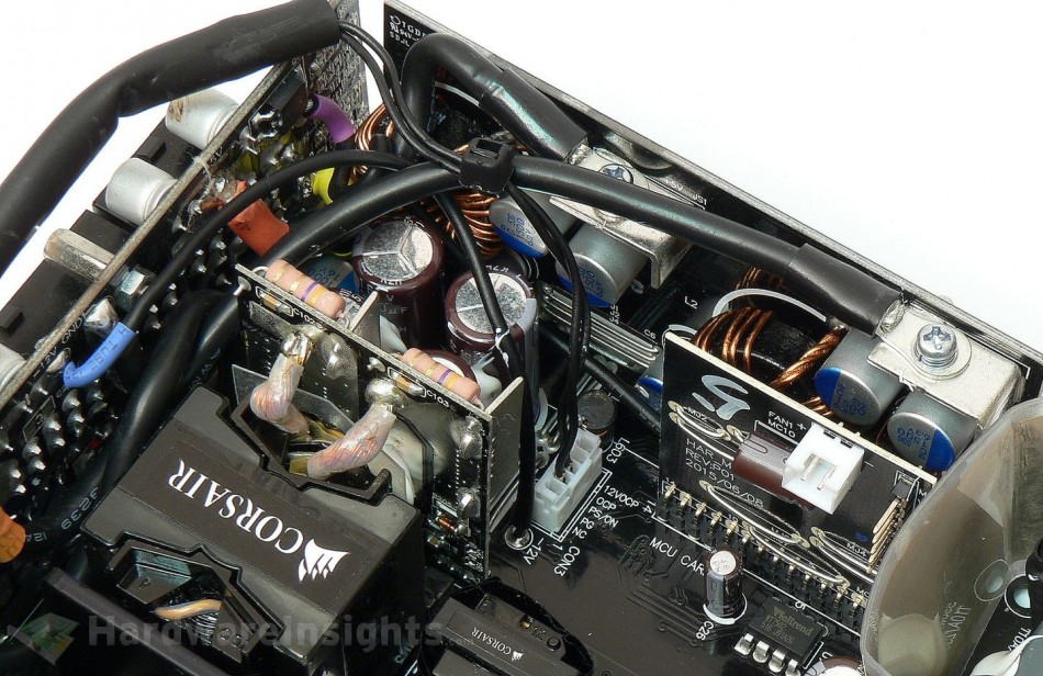
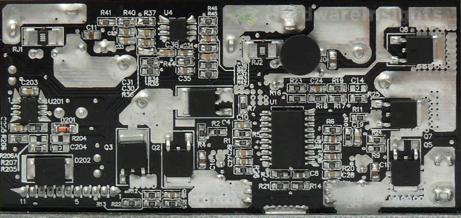
There are two pairs of Sinopower SM4021NAKP (100/40 A at 40 V and 25 °C, Rds(On) 1.9 mΩ at 25 A and 125 °C) transistors in modern DFN5x6-8 package (also known as HSON or LFPAK – each manufacturer has its own name) used for +12V rectification. There is also an extra spot for two more transistors for higher-power versions of the power supply on the rectification module. The Texas Instruments UCC27324D low-side driver is used to control the transistors. Four big (D12.5) NCC KZH 3300/16 capacitors with a single PSG 1000/16 polymer then filter the voltage with two more PSG 470/16 on the DC-DC daughterboard. Their output then use two 1500/6.3 polymers for each rail (+3.3/+5 V). Three Ubiq QM3004D (55/110 A at 30 V and 25 °C, 8.5 mΩ at 30 A and with Vgs of 10 V or 14 mΩ at 15 A and 4.5 V) transistors act as the switchers for each DC-DC module, while the Anpec APW7159C controls them all.
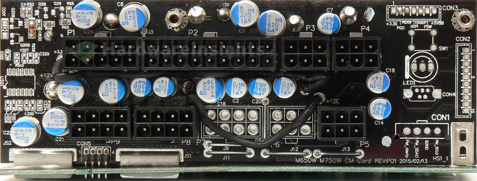
So far the APW7159 controller did not really show too good voltage regulation so I am curious if we will see the same mainstream performance here. The −12 V rail is somehow generated on the +12 V rectification module as well and has a single NCC KY 1000/16 capacitor for filtration (the rectification part of the circuit is then located on the DC-DC module board which means dragging AC power all the way through the secondary). But as for the filtering, we are not done yet, there is a whole bunch of polymer capacitors on the modular board. A single 470/16 for the −12 V rail; five more for +12 V with four 270/16; 820/6.3 and two 560/6.3 for +3.3 V (and the same for +5 V). Couple more capacitors are soldered directly on the wiring near the connectors, 560/6.3 on the lower rails and 330/16 (ATX 12 V, PCIe) with 470/16 (Main ATX) on the +12 V rail.
Then there is another QM3004D transistor which seems to supply the +5 V SB output from the +5 V rail when it is running (power supply is on) to save some power (stand-by supply efficiency is slightly worse), for that purpose there is one more 470/16 polymer on the +5 V rail. Secondary OVP/UVP monitor (and as usually, Power Good generator and PWR On monitor) is Weltrend WT7502. It does nothing more, OCP and OPP are monitored by their belonging controllers (on DC-DC or rectification module) with the help of couple comparators/operational amplifiers. As for the fan controller, it uses no thermistor sensor but has its own dedicated daughterboard carying Microchip PIC16F1503 microcontroller which monitors output power, however, there may still be some thermal sensor somewhere as the unit is supposed to have over-temperature protection. We will see.
Build quality
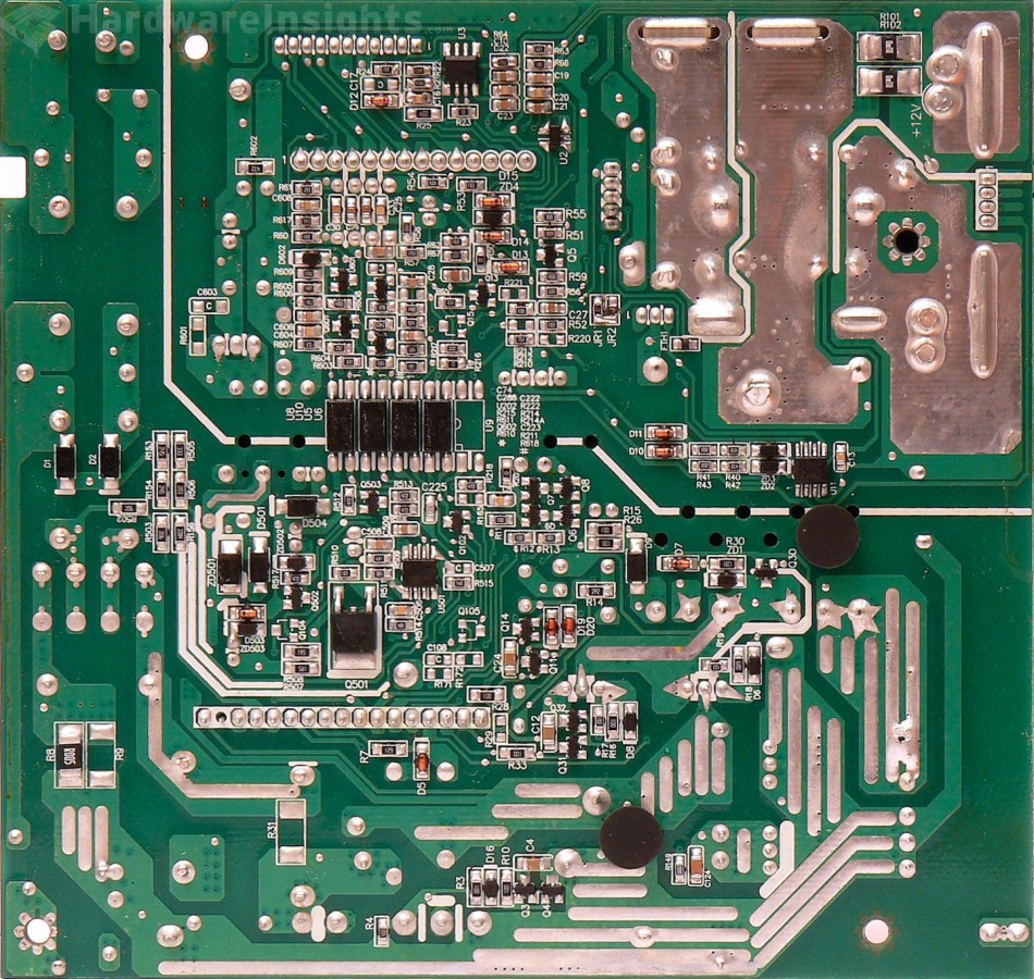
As usual I will focus on the overall build quality and other things like electrical safety here as the quality of the components used was already discussed before. Primary and secondary side separation is good. Where needed, there is an extra layer of insulation, which is not on too many places here. Thermistor is not covered with heatshrink though. Conductive paths are reinforced, but not really that much, the layer of solder is minimal – at least on the main board. That is also the reason why the PFC coil is soldered so badly on both sides.
Also the manually-soldered cables are so messy, the solder flux has not been cleaned at all, especially on the rectification module (cables from main transformer). With this level of soldering it is almost amazing that I only found three solder balls. That would be 8 points less for soldering quality for the Corsair RM550x.


