Contents
- 1Introducing the Corsair SF600
- 1.1Packaging and accessories
- 2Connectors & cabling
- 2.1Casing & cooling
- 3Input filtering
- 4Primary side
- 4.1+5 V stand-by rail
- 5Secondary side
- 5.1Build quality
- 6Load testing
- 6.1Loading +5 V SB
- 6.2Hold-up time
- 6.3Combined loading
- 6.4Combined loading ripple
- 6.5Crossloading, overloading
- 6.6Crossloading, overloading ripple
- 6.7Fan speed, temperatures and noise
- 7Conclusion and evaluation
- 7.1Thanks
- 7.2Discussion
Primary side
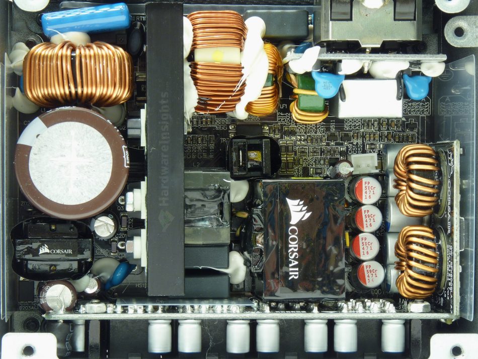
The primary side begins with the input bridge rectifier, the GBU1508 which shares common heatsink. It can handle 15 A at 100 °C and 800 V continuously, or 240 A peak (for 8.3 ms). Its voltage drop (counting for losses) is 1.1 V per diode at 7.5 A. There is just a single powerful N-FET in the boost-type PFC circuit, the Alpha & Omega Semiconductor AOK42S60 (39/166 A at 600 V and 25 °C, RDS(On) 280 mΩ at 21 A and 150 °C, 99 mΩ at 25 °C) in a TO-247 package. The diode is the Cree C3D06060A (8.5 A at 600 V and 135 °C, 200 A peak for 10 μs at 25 °C, drop of 1.8 V at 6 A and 25 °C, 2.4 V at 175 °C). The PFC coil seems capable enough, it has reasonably large core and thick enough wire. Notice the two layers of PCB material under the coil.
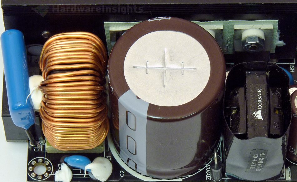
The bulk capacitor that gets charged from the PFC is a Nippon Chemi-Con KMZ 470 μF/420 V. I measured its actual capacitance at 416 μF. This is the newest downsized series from NCC with minimum lifetime of 2000 hours at its maximum temperature (105 °C) and ripple. The switching transistors are two Fairchild SuperFET II FCP104N60F (37/114 A at 25 °C and 600 V, RDS(On) 104 mΩ at 18.5 A) in the resonant forward configuration. All the remaining power silicon here comes in a TO-220 package, and together with the PFC transistor all are mounted to a common primary heatsink.
As for the driving circuitry, there is the latest Champion Micro CM6502UHHX PFC controller. The three-way switching/synchronous rectification resonant controller (two PWM modes and FM) is the usual CM6901X. As usually, it is physically located on the secondary side. There is also the CM03X microchip to reduce no (or low) load losses. This is one of the two ICs which are fed directly from behind the input rectifier through a chain of high-resistance SMD resistors. The main transformer has a 32mm core. After a long time, this is what I call a serious overbuild and for that the SF600 gets two extra points!
+5 V stand-by rail
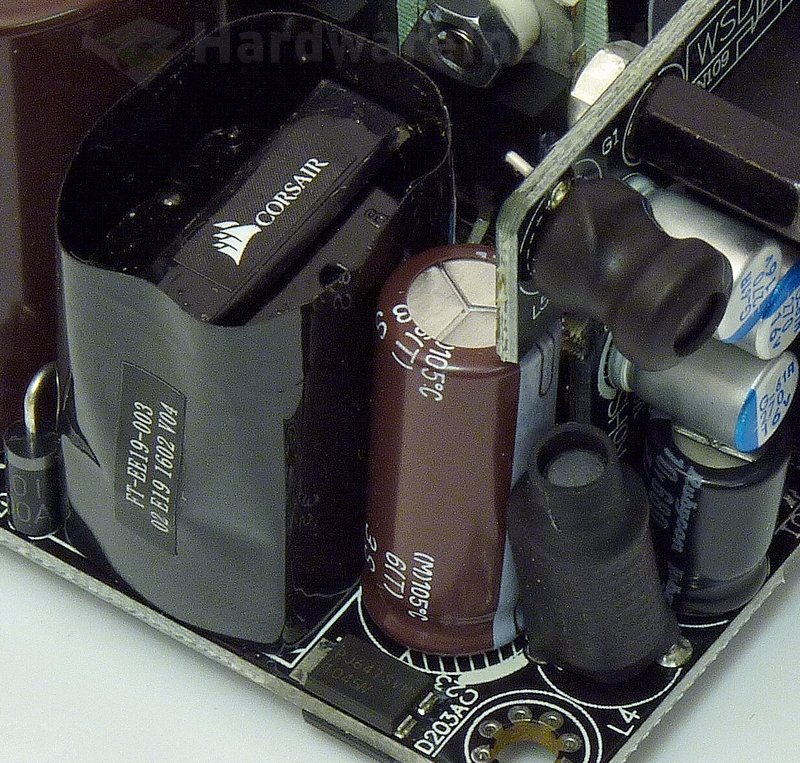
The stand-by rail PWM controller is the second IC in the SF600 powered directly from after the input rectifier. It is the Leadtrend LD7750R and because it is very small coming in SMD SOP-7 package, it lacks the transistor. Separate FET is used instead, the Advanced Power Electronics AP04N60H-H-HF (2.2/15 A, 700 V, 2.8 Ω at 2 A) in TO-252 package. The transformer is EE-19.
Two SMD Schottky diodes are used, soldered from both sides of the board in parallel, the Panjit Semiconductor SVM1045V (10/275 A at 45 V, drop of 0.47 V at 10 A and 25 °C) in a TO-277 package. In the Pi filter there is a Chemi-Con KZE 1200/16 and a Rubycon ZLH 680/10 capacitor. Not bad though some more modern series than the KZE could have been used.


