Contents
- 1Introducing the Corsair SF600
- 1.1Packaging and accessories
- 2Connectors & cabling
- 2.1Casing & cooling
- 3Input filtering
- 4Primary side
- 4.1+5 V stand-by rail
- 5Secondary side
- 5.1Build quality
- 6Load testing
- 6.1Loading +5 V SB
- 6.2Hold-up time
- 6.3Combined loading
- 6.4Combined loading ripple
- 6.5Crossloading, overloading
- 6.6Crossloading, overloading ripple
- 6.7Fan speed, temperatures and noise
- 7Conclusion and evaluation
- 7.1Thanks
- 7.2Discussion
Secondary side
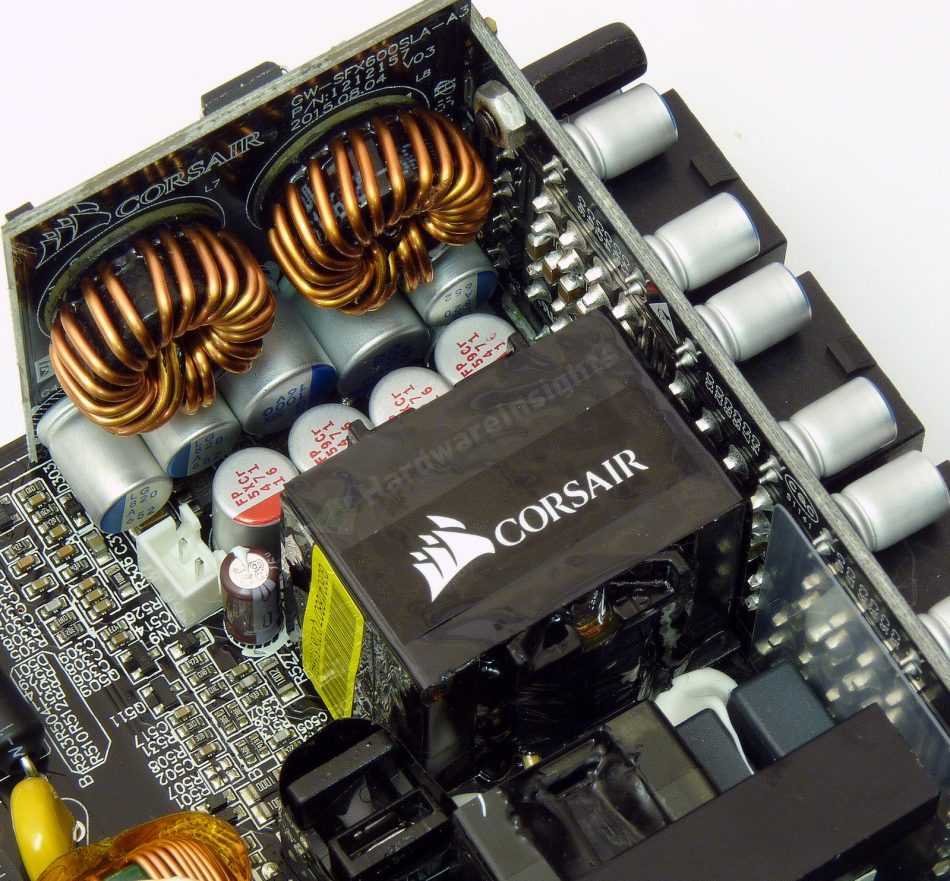
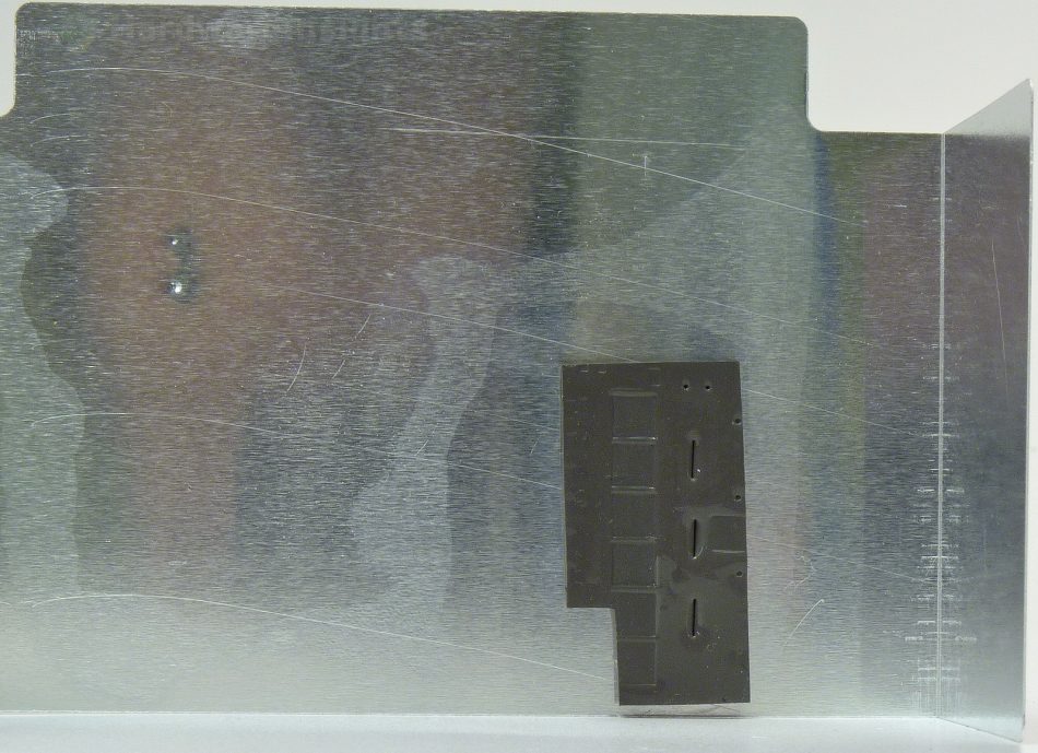
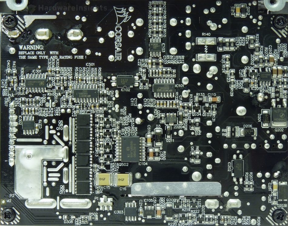
As we have already established, the SF600 synchronous rectification is driven by the CM6901X. It is connected with primary side using Silicon Labs Si8230BD isodriver. The rectification itself uses 2× three Alpha & Omega transistors, the AON6590 (100/400 A at 25 °C and 40 V, 0.99 mΩ at 25 °C, 1.55 mΩ at 125 °C) in the DFN5x6 SMD package. Their losses are so low they actually have no heatsink whatsoever. Instead, GreatWall put an aluminium plate around the board, thermally connected to the transistors using a silicon pad in an opening in the insulation foil. There is also one thermistor near them which most likely regulates the fan speed.
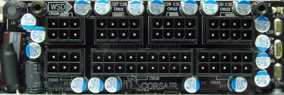
The filtering capacitors for the +12V output are four Fujitsu functional polymer of unknown series, 470/16. There are also two Chemi-Con PSG 1000/16 on the board carrying DC-DC modules and large number of another PSG 270/16 on the modular board. Plus a large number of SMD ceramic capacitors which also add couple hundred μF altogether. The total capacity is about 7.3 mF.
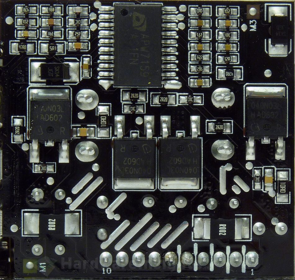
The DC converters are both on a single daughterboard, with the Anpec APW7159 buck controller running both. Two Infineon IPD040N03L G (90/400 A at 25 °C, 30 V, 5.9 mΩ at 30 A) transistors in TO-252 package do the switching for each converter. Each has two Nichicon LG 820/10 for filtering plus a few of the PSG 270/16 (and maybe the ceramic capacitors) on the modular board also filter the +3.3 and +5 V rails. The total capacity on both rails is approx. 2.4 mF.
The output of the DC-DC board leads directly to the modular board as they are both soldered together. The modular board is also directly soldered to the main PCB where it sources the +12 V from, plus stand-by voltage and other signals (feedback, PWR On etc.).
The secondary supervisor is Silicon Touch Technology PS229. Besides the ordinary functions, this one also monitors OCP on two 12V rails and also the +3.3/+5 V rails. It is possible some other protections are connected to the current sense inputs, like the OTP as there are also two Advanced Analog Circuits AS358A dual operational amplifiers in the SF600. As for the −12V rail, it seems to be generated using the Texas Instruments TPS54231 DC-DC converter. Couple of the PSG 270/16 capacitors also filter this rail. I think I can add two more points for the overbuilt of the secondary side.
Build quality
As usual, I’ll focus on the overall build quality and other things like electrical safety here, as the quality of the components that were used has already been discussed before. The separation between the primary and secondary sides is good. As the modular board is very close to the primary side, there is a slot between these two parts which an insulation foil is put through. The varistor is not sleeved with heatshrink though, but the thermistor is. The amount of silicone is reasonable plus it also acts as electric insulation in couple occasions.
Many of the tracks are reinforced with layers of solder, the short +12V path from the transistors to the modular board is reinforced with a copper plate which was screwed in and then also flooded with solder. A quality double-sided glass epoxy PCB (or something similar) is used. The soldering is very good though I would not call it perfect. Some joints could still be slightly better. There is also some residue around the AC input joints and overall the board looks somewhat dirty. I found no solder balls so this is very good job. I would say this is good for just minus one point of the basic build quality score.
