Contents
- 1Introducing the Crono PS350N
- 1.1Packaging and accessories
- 2Connectors & cabling
- 2.1Casing & cooling
- 3Input filtering
- 4Primary side
- 4.1+5 V stand-by rail
- 5Secondary side
- 5.1Build quality
- 6Load testing
- 6.1Loading +5 V SB
- 6.2Hold-up time
- 6.3Combined loading
- 6.4Combined loading ripple
- 6.5Crossloading, overloading
- 6.6Crossloading, overloading ripple
- 6.7Fan speed, temperatures and noise
- 7Conclusion and evaluation
- 7.1Thanks
- 7.2Discussion
Primary side
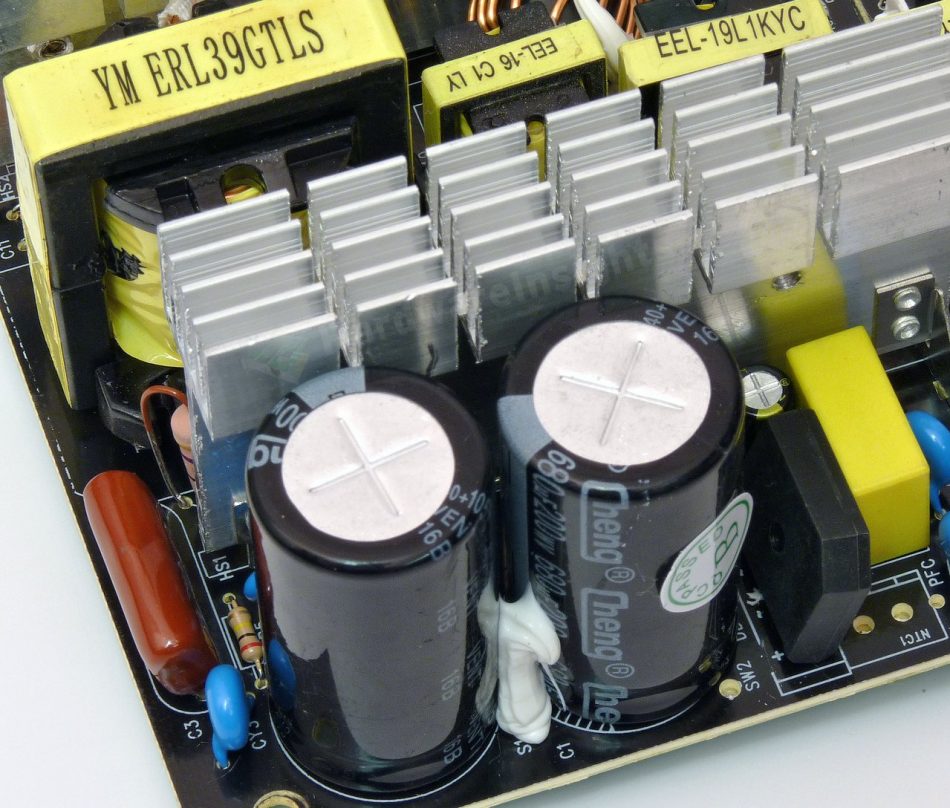
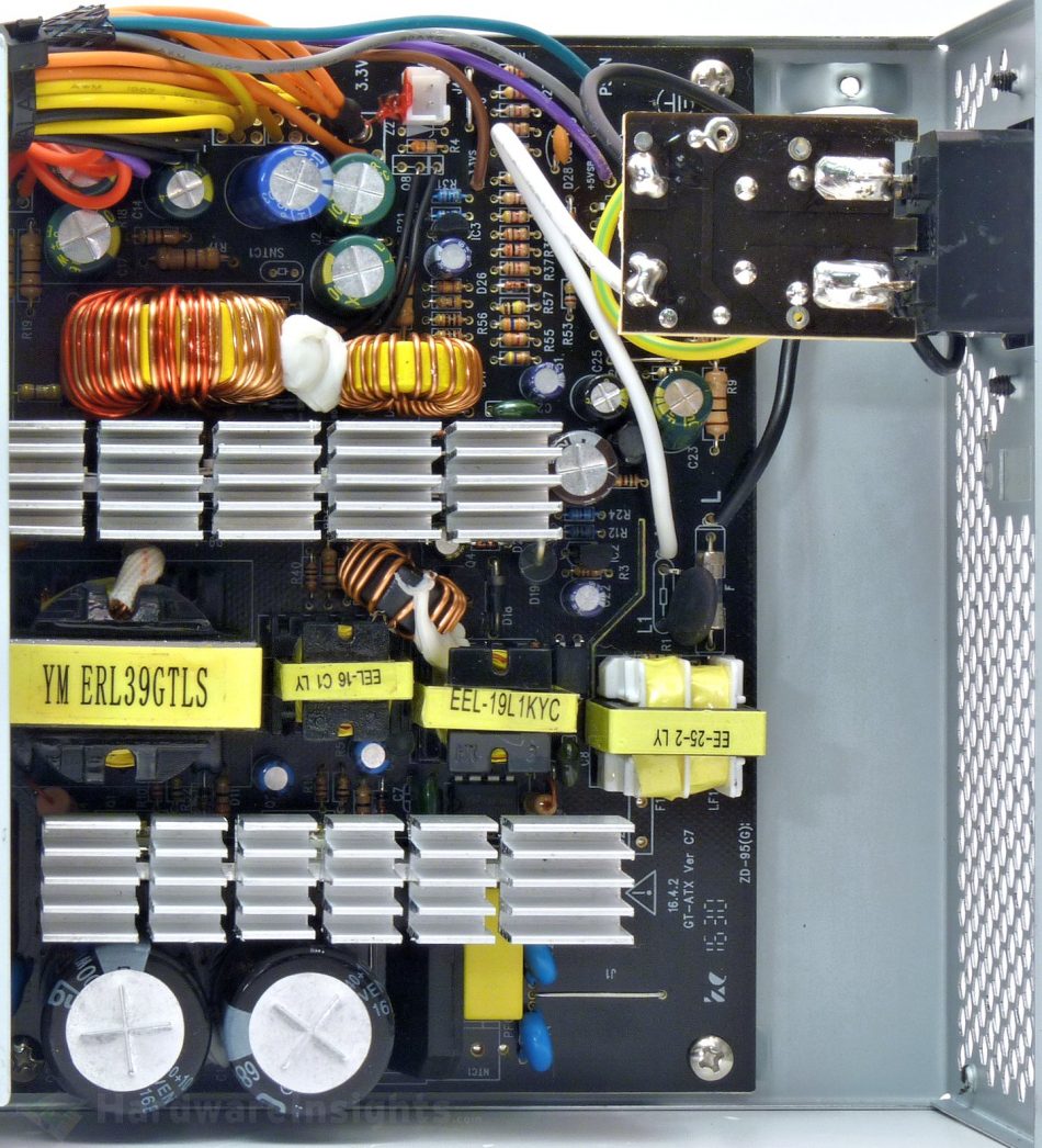
The primary side of the PS350N starts with input bridge rectifier, the KBL406. This is one of those bridges which basically consist of four discrete diodes molded into a single plastic package. It is thick, limited to 4 A continuously (200 A surge) at 50 °C ambient and does not mount to a heatsink. Maximum voltage is 800 V, voltage drop 1.1 V per diode. While there is a spot for connector from passive PFC coil, this unit has no power factor correction mechanism whatsoever. Instead, a solder bridge was used to complete the circuit. I have no ability to measure harmonics, but even from the power factor itself it will be pretty evident this unit has no chance of passing the international standard IEC 61000-3-2.
As for the bulk capacitors, as the topology is old, two 200V capacitors in series are still used even though the voltage doubler is absent (but there are spots for it). They are Cheng (or ChengX) 680 μF/200 V for 105 °C. They are garbage fakes with true capacitance under 470 μF, the effective capacitance is then about 235 μF. The switchers are in the half-bridge configuration (as expected). But surprisingly they are not the ordinary 13007, rather the higher-power 13009 BJTs. So there may be a slight chance it will actually deliver the rated power. Controller/supervisor is the East Semiconductor Technology EST7502C, located on secondary side.
The primary heatsink is not paper-thin and it has some reasonable surface area. The main transformer is labeled as ERL-39 but it only has a -35 core so this seems like a fake marking to me.
+5 V stand-by rail
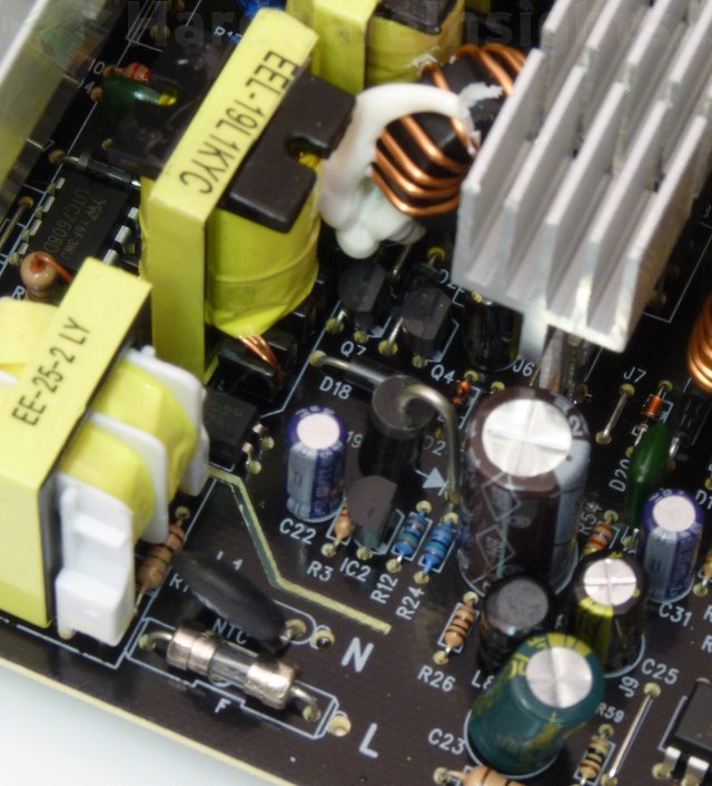
The stand-by rail uses PWM controller with integrated transistor, the UTC7608D. I found no datasheet though some sources suggest it is a copy of SanKen STR-60xx family. A ChengX 47/50 capacitor filters its power supply line.
The transformer here is EEL-19 and the one-way Schottky rectification diode is 1N5822 (3/80 A at 40 V), in DO-201AD package. Output filtering consists of two more ChengX caps, 1000 μF/16 V and 470 μF/10 V. There is even a coil in this filter.


