Contents
- 1Introduction
- 1.1Packaging and accessories
- 2Connectors & cabling
- 2.1Casing & cooling
- 3Input filtering
- 4Primary side
- 4.1+5 V stand-by rail
- 5Secondary side
- 5.1Build quality
- 6Load testing
- 6.1Loading +5 V SB
- 6.2Combined loading
- 6.3Combined loading ripple
- 6.4Crossloading, overloading and the Sweater contest
- 6.5Crossloading, overloading ripple
- 7Conclusion and evaluation
- 7.1Thanks
Primary side
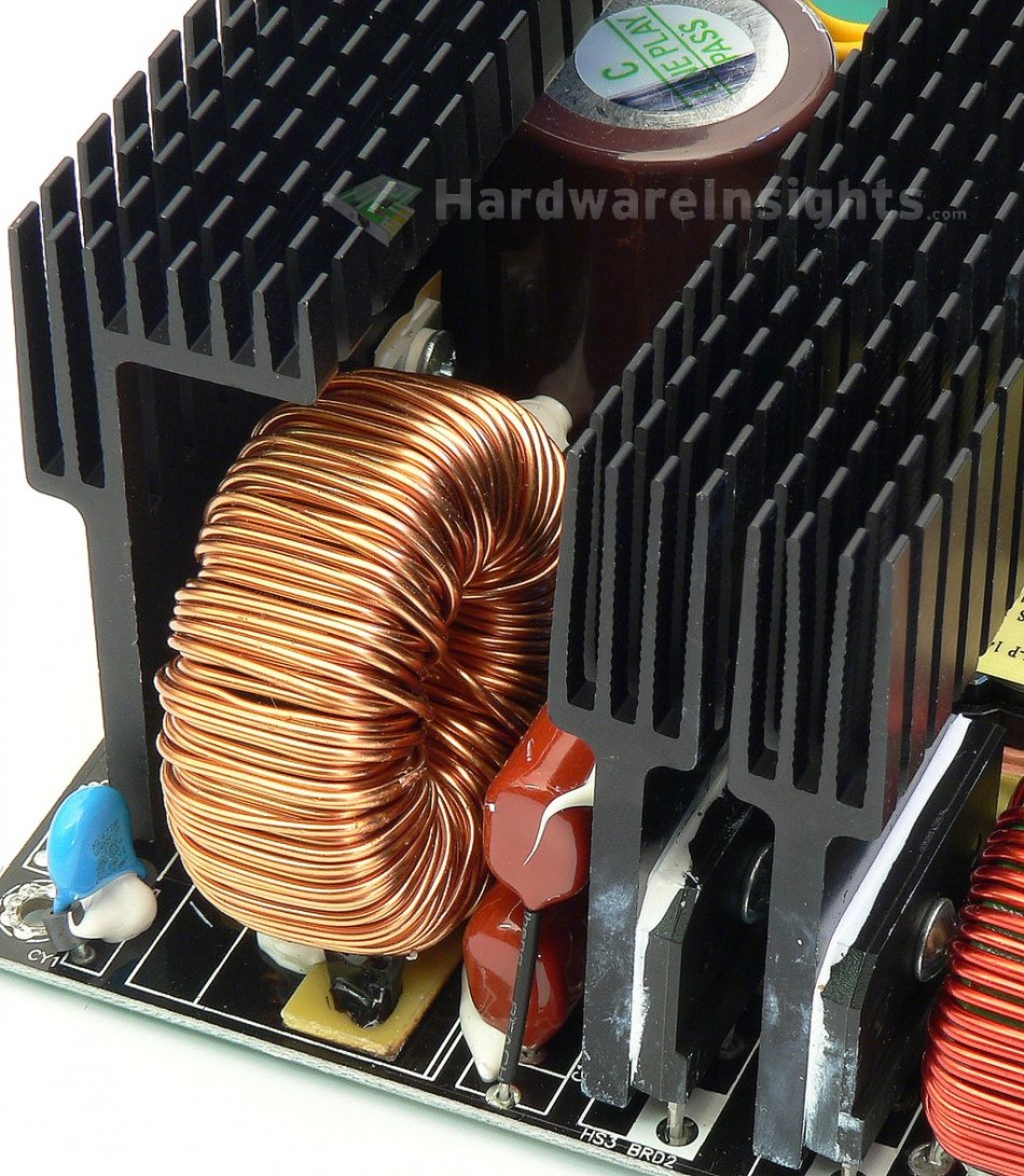
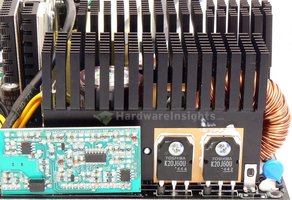
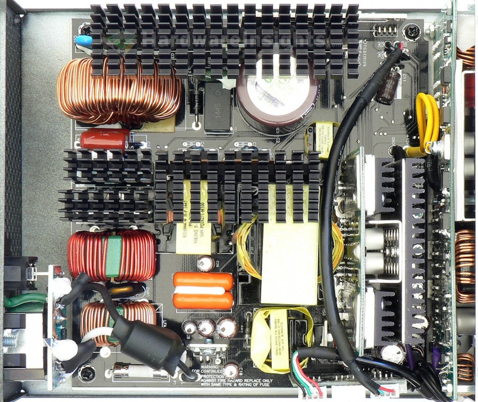
The primary side begins, as always, with a bridge rectifier, the Shindengen LL25XB60. There are actually two of them in parallel and each has its own black heatsink! Each handles current of 25 A continuously at 600 V and 113 °C (case)/945 A surge (for 1 ms) at 25 °C (junction). Voltage drop is only 0.92 V per diode (at 12.5 A). The transistors in PFC (boost-type) circuit are two in parallel, Toshiba TK20J60U (20 A continuous/40 A pulsed at 25 °C and 600 V, on resistance (Rds(On)) is 190 mΩ at 10 A and 25°C) in TO-3P package. The power diode in PFC is a Cree C3D08060A (8 A continuously at 600 V and 150 °C, 220 A peak at 25 °C for 10 μs, voltage drop of 2.4 V at 8 A and 175 °C) in TO-220-2 package. These three parts have their own big black heatsink. The PFC coil is very massive (approx. 45 mm in diameter) with two-wire winding.
The capacitor charged by PFC circuit is Nippon Chemi-Con KMQ 470 μF/400 V for 100 °C (measures 404 μF). While 420V part would be preferred, it at least has specified lifetime of 2000 hours at 105 °C. Switching transistors are another two Toshiba TK20J60U, mounted on a separate heatsink, again an aluminium one with black color. The PFC circuitry is on a separate daughterboard in front of the PFC heatsink, however, there is no insulation or spacer between the board and the heatsink. The air gap should be enough, but the board must be soldered perfectly under right angle. The PFC is controlled by a combiínation of Champion Micro CM6502TX and CM03X for which I exclusivelly acquired datasheet so now I know it is intended to lower phantom power and improve no-load consumption. The third chip is an LM393 comparator from STMicro, most likely used for the digital function (to measure input power).
Switching controller is CM6901X physically located on the bottom of secondary side. It has three distinct operation states – PWM regulation for light load, series resonant/LLC resonant control with frequency modulation and then series resonant control with PWM regulation again for very high loads. Its supply power is filtered by Chemi-Con KY 47μF/50V capacitor, the same as on feedback. The main transformer is quite massive too, it has thick core, 43mm wide. The input filtration and primary side is effectively taking almost 2/3 of the space on the main board. I like how overbuilt the unit is so it gets three extra points.
+5 V stand-by rail
The stand-by rail uses Power Integrations TOP265EN PWM controller with integrated transistor for 725 V in a special eSIP-7C package. It is rated for 57 W in open-frame universal-input applications, and is mounted to a tiny heatsink. It claims to have its own set of protections including over-current/over-power and even over-temperature! So when this little fella overheats, the whole Digifanless shuts down. Nice. All of the feedback capacitors are Nippon Chemi-Con KY.
Behind the EEL-22 transformer is the Diodes SBR10U60CTFP Super (schottky) barrier rectifier (10/150 A at 110 °C and 60 V, drop of 0.62 V at 10 A and 25 °C) in TO-220F package. It is mounted on a separate tiny heatsink. The output filter consists of two NCC KY capacitors, 2200/10 and 1000/10.


