Contents
- 1Introducing the Fortron FSP200-50GSV-5K (85)
- 1.1Packaging and accessories
- 2Connectors & cabling
- 2.1Casing & cooling
- 3Input filtering
- 4Primary side
- 4.1+5 V stand-by rail
- 5Secondary side
- 5.1Build quality
- 6Load testing
- 6.1Loading +5 V SB
- 6.2Hold-up time
- 6.3Combined loading
- 6.4Combined loading ripple
- 6.5Crossloading, overloading
- 6.6Crossloading, overloading ripple
- 6.7Fan speed, temperatures and noise
- 7Conclusion and evaluation
- 7.1Thanks
- 7.2Discussion
Secondary side
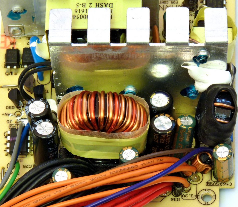
The secondary side of the FSP200-50GSV-5K uses three Schottky rectifiers, each one is different. The +3.3V rail uses magamp coil to derive from +5 V and Diodes SBR30A40CT (30/250 A, 40 V, 0.60 V @30 A). For the +5 V rail itself there is PFC Device Corporation PFR30V30CT (30/280 A, 30 V, 0.44 V @15 A/25 °C, 0.37 V @125 °C) and finally PFR20L60CT (20/180 A, 60 V, 0.65 V @10 A/25 °C, 0.56 V @125 °C) for +12 V. All three devices share common secondary tin-coated copper heatsink. The -12V rail uses small diode which rectifies output from special winding on the common inductor. There’s Teapo SY 1000/16 to filter this rail. The other rails always have custom C(r)apXon GF 470/16 D6.3×20mm after their respective Pi coils while the first cap varies: Teapo SY 1000/16 for +12 V, C(r)apXon LZ 1500/10 for +5 V and custom Teapo SZ 2200/6.3 for +3.3 V.
There is only the very basic 8-pin Silicon Touch Technology PS113 for OVP, UVP and signal control. So there is NO OCP capability in this unit and it would be interesting to see if OPP actually works. The fan speed controller uses thermistor probe screwed and silicone-glued to the secondary heatsink.
Build quality
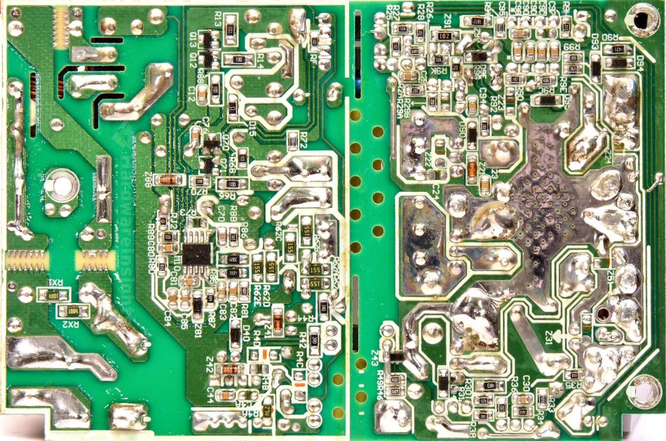
As usual, I’ll focus on the overall build quality and other things like electrical safety here, as the quality of the components that were used was already discussed before. The separation between the primary and secondary sides is good, there is even some extra creepage slot under the optocouplers and some openings under both transformers for extra cooling. The thermistor is not present but varistor is sleeved with heatshrink. Silicone was used to fix components in place.
As the board is smaller and quite simple, there is not much to go wrong here. There are a few joints which deserve resoldering and as usually from FSP, many electrodes could use better trimming. Other than that I only found single solder ball solidly stuck in soldering flux so no problem here. I think this is good for the task, only two points down from the base evaluation because of the few worse solder joints.


