Secondary rectifier ratings in forward topology
The way used by Hardware Secrets for calculating their current capacity isn't exactly correct and nor is merely adding their nominal ratings together...
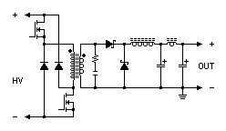
The simplified circuit of a basic two-transistor forward converter (there is also a one-transistor version, which is a bit less efficient as it requires a primary-side snubber, but otherwise isn't much different) has the following schematic:

The components on the input are not shown, but not relevant to this topic. The two (small) fast recovery diodes to the left of the transformer return the energy from its inductive "kick-back" to the primary capacitors when the switchers turn off. The resistor and ceramic capacitor in series across the transformer secondary (and between the anodes of the two Schottky diodes) are a snubber (how those work is not relevant to this topic, but suffice to say that their purpose is to absorb voltage spikes). (In flyback, in case you're wondering, the secondary-side snubber is directly across the diode.) The diode whose anode is connected to ground is the "freewheeling" rectifier. The large coil between the cathodes and the first capacitor is the mag-amp, with the small ferrite coil between the two capacitors for additional filtering.
The thing about these designs is that the rectifier connected to the "top" of the transformer winding in the picture (I call it the pulse rectifier, as it conducts the pulses from the transformer) is loaded for the "on" time of the switcher, and the "freewheeling" rectifier loaded for the "off" time. This is not a problem with using the two diodes in a single component as they are on the same chip, and will stay at about the same temperature as each other. But if you use multiple parts with any wiring arrangement other than every part having one diode as the pulse rectifier and one for freewheeling, things get a lot more complicated, and nominal capacity will only be attainable at a specific duty cycle.
The current capacity of a diode is referred to as "maximum average forward current" which means the instantaneous current multiplied by the duty cycle. So based on this rule, an SBL2045CT could handle 20A at a 100% (continuous) duty, 30A at 67% (two thirds), 40A at 50% (half), 50A at 40% (two fifths), 60A at 33% (one third), or 80A at 25% (one quarter). In practice, though, the instantaneous forward voltage rises with higher instantaneous forward current. But there's no simple rule for that.
Here's my formula:
Instantaneous current per diode = output current / number of parallel diodes (has to be done separately for the pulse and freewheeling rectifiers)
Overall average current in a dual-diode part = ([I(A)]*[D(A)])+([I(B)]*[D(B)]) where I is the instantaneous current in the diode and D is its duty cycle, while (A) and (B) distinguish between the two individual diodes
I've heard a typical operating duty cycle is one third. Freewheeling occurs during the gap between switching pulses, so in that case the freewheeling rectifier would be on for two thirds of the cycle. One-quarter duty would have freewheeling for the other three quarters of the cycle, two-fifths duty would have freewheeling for the other three fifths, and I think you get the idea now.
Onto the examples:

With identical parts in all of them...
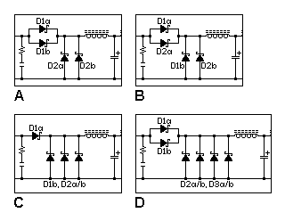
Example A works perfectly if the duty cycle is exactly 50%, but if it's 33%, the safe output is reduced by 25%!!!!! To optimise it for 33%, you would want to choose the rectifiers so that D2 has double the rating of D1.
Example B solves that problem, simply by swapping the connections.
Example C is the arrangement used for +5V in the Dell H305P-01. The optimal duty cycle is 25%. With a 33% duty cycle, the capacity is reduced by 10% (not the 25% you might expect if you didn't take into account that the change will also reduce dissipation in the freewheeling diodes).
Example D uses three parts and is optimised for 33% duty.
Try out the calculation for yourself...
The simplified circuit of a basic two-transistor forward converter (there is also a one-transistor version, which is a bit less efficient as it requires a primary-side snubber, but otherwise isn't much different) has the following schematic:
The components on the input are not shown, but not relevant to this topic. The two (small) fast recovery diodes to the left of the transformer return the energy from its inductive "kick-back" to the primary capacitors when the switchers turn off. The resistor and ceramic capacitor in series across the transformer secondary (and between the anodes of the two Schottky diodes) are a snubber (how those work is not relevant to this topic, but suffice to say that their purpose is to absorb voltage spikes). (In flyback, in case you're wondering, the secondary-side snubber is directly across the diode.) The diode whose anode is connected to ground is the "freewheeling" rectifier. The large coil between the cathodes and the first capacitor is the mag-amp, with the small ferrite coil between the two capacitors for additional filtering.
The thing about these designs is that the rectifier connected to the "top" of the transformer winding in the picture (I call it the pulse rectifier, as it conducts the pulses from the transformer) is loaded for the "on" time of the switcher, and the "freewheeling" rectifier loaded for the "off" time. This is not a problem with using the two diodes in a single component as they are on the same chip, and will stay at about the same temperature as each other. But if you use multiple parts with any wiring arrangement other than every part having one diode as the pulse rectifier and one for freewheeling, things get a lot more complicated, and nominal capacity will only be attainable at a specific duty cycle.
The current capacity of a diode is referred to as "maximum average forward current" which means the instantaneous current multiplied by the duty cycle. So based on this rule, an SBL2045CT could handle 20A at a 100% (continuous) duty, 30A at 67% (two thirds), 40A at 50% (half), 50A at 40% (two fifths), 60A at 33% (one third), or 80A at 25% (one quarter). In practice, though, the instantaneous forward voltage rises with higher instantaneous forward current. But there's no simple rule for that.
Here's my formula:
Instantaneous current per diode = output current / number of parallel diodes (has to be done separately for the pulse and freewheeling rectifiers)
Overall average current in a dual-diode part = ([I(A)]*[D(A)])+([I(B)]*[D(B)]) where I is the instantaneous current in the diode and D is its duty cycle, while (A) and (B) distinguish between the two individual diodes
I've heard a typical operating duty cycle is one third. Freewheeling occurs during the gap between switching pulses, so in that case the freewheeling rectifier would be on for two thirds of the cycle. One-quarter duty would have freewheeling for the other three quarters of the cycle, two-fifths duty would have freewheeling for the other three fifths, and I think you get the idea now.
Onto the examples:
With identical parts in all of them...
Example A works perfectly if the duty cycle is exactly 50%, but if it's 33%, the safe output is reduced by 25%!!!!! To optimise it for 33%, you would want to choose the rectifiers so that D2 has double the rating of D1.
Example B solves that problem, simply by swapping the connections.
Example C is the arrangement used for +5V in the Dell H305P-01. The optimal duty cycle is 25%. With a 33% duty cycle, the capacity is reduced by 10% (not the 25% you might expect if you didn't take into account that the change will also reduce dissipation in the freewheeling diodes).
Example D uses three parts and is optimised for 33% duty.
Try out the calculation for yourself...