Contents
- 1Introducing the Linkworld Stability Power LPJ9-25 420 W
- 1.1Packaging and accessories
- 2Connectors & cabling
- 2.1Casing & cooling
- 3Input filtering
- 4Primary side
- 4.1+5 V stand-by rail
- 5Secondary side
- 5.1Build quality
- 6Load testing
- 6.1Loading +5 V SB
- 6.2Hold-up time
- 6.3Combined loading
- 6.4Combined loading ripple
- 6.5Crossloading, overloading
- 6.6Crossloading, overloading ripple
- 6.7Fan speed, temperatures and noise
- 7Conclusion and evaluation
- 7.1Thanks
- 7.2Discussion
Secondary side
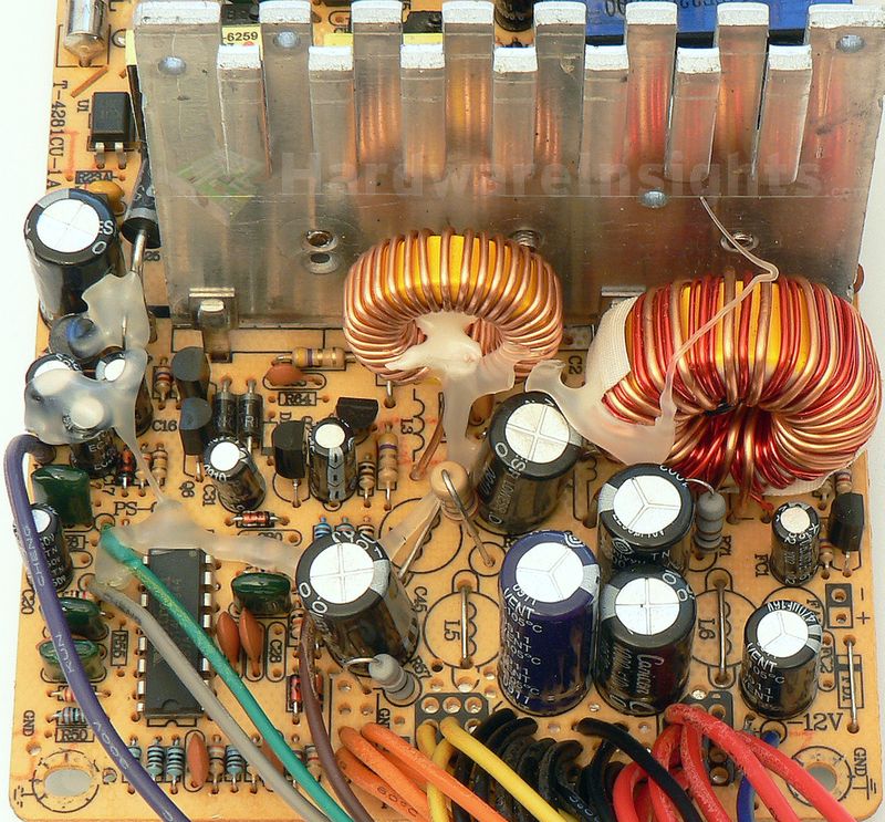
On the secondary side of the LPJ9-25 we can see the usual scenery: +3.3 V magamp and couple TO-220 Schottky rectifiers. There is MBR20100CT (20/150 A at 100 V and 120 °C, drop of 0.95 V at 20 A and 25 °C, 0.85 V at 25 °C) for +12 V rail. For +3.3/+5 V there are the same rectifiers, Jilin Sino Microelectronics SBL2040CT (20/150 A at 40 V and 100 °C, drop of 0.6 V at 10 A and 25 °C). Remember the +5V rail is supposed to deliver 34 A. While most rectifiers have some reserve, I doubt it is 70 %. There are NO Pi coils whatsoever in the output filtering though there are spots for them. The +12V rail does not even have the first capacitor installed, the remaining ones are Canicon and Fuhjyyu. Oh my.
The already mentioned Weltrend microchip takes care of the UVP and OVP, that is all. There is however a fan control circuit installed. It consists of thermistor sensor (placed inside the common filtering choke) and Unisonic Technologies 2SD1857L, a TO-92 NPN transistor. I guess the choke will be running pretty hot then.
Build quality
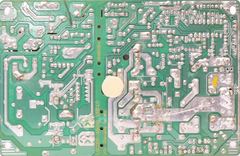
As usual, I’ll focus on the overall build quality and other things like electrical safety here, as the quality of the components that were used was already discussed before. The separation between the primary and secondary sides is good, there are even some extra creepage slots to separate unrectified path from the rectified primary. Plus also some holes under the transformers for better cooling. There is no insulation film under the board, but it at least has some plastic spacer. The electrodes are trimmed OK. The soldering is not so tragic as you would expect from such a cheap unit. There are many problems but most have been better or worse addressed by manual resoldering.
Plus there is also some path reinforcement. Nothing I would write about, but it is at least half-decent. Nobody cleaned the board afterwards so there is some soldering flux. But it has been cleaned before and there are no solder balls at all! I would even add a few points for that if I did not already know it’s going to fail. The strange fibres you could have seen on the previous images are remains of hot glue. This was used here to fix components in place. If you ever worked with hot glue pistol, you know it tends to do that. This stuff is definitely not good for PSU. First, it cracks and some pieces may stick the fan. Second, when the unit heats to very high temperatures – which such wonders do – it melts. Then it starts decaying, I think it may also become conductive or flammable.


