Contents
Addendum – Working on the unit
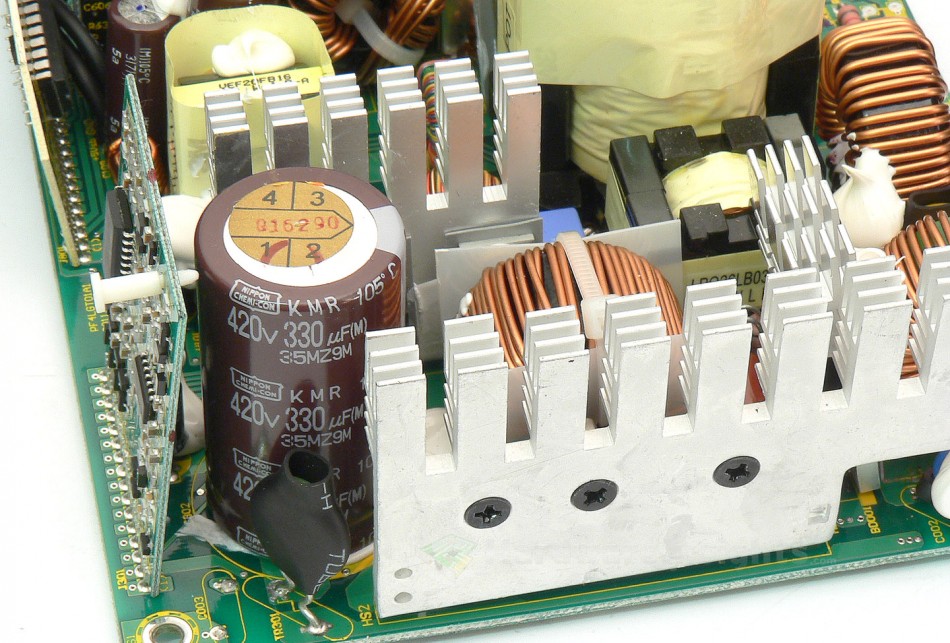
The worst problem I experienced with this unit was the ripple. Those who observed carefully may have noticed that there are some parts missing in this unit: One Y capacitor on the primary side (between earth ground and the unit’s primary common) and one capacitor in the +12 V filtering section.
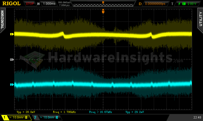
I’ve added a single Nippon Chemi-Con PSC 330/16 polymer capacitor and one 2.2nF ceramic as the Y cap. I’ve also since been looking for a way to decrease the high-frequency ripple, and I came up with a solution. Ceramic capacitors usually work well for this type of ripple, but the only problem was obtaining them, and then locating a spot on where to solder them. I managed to salvage a couple 1206 capacitors (approx. 8μF) from an old Pentium III motherboard which was going to be recycled anyways, and since I could find nowhere else, I soldered them directly to the legs of the electrolytic filtering capacitors in this unit. So two capacitors each have been added to the +3.3 V, +5 V and stand-by rail, one capacitor on each side of every Pi filter.
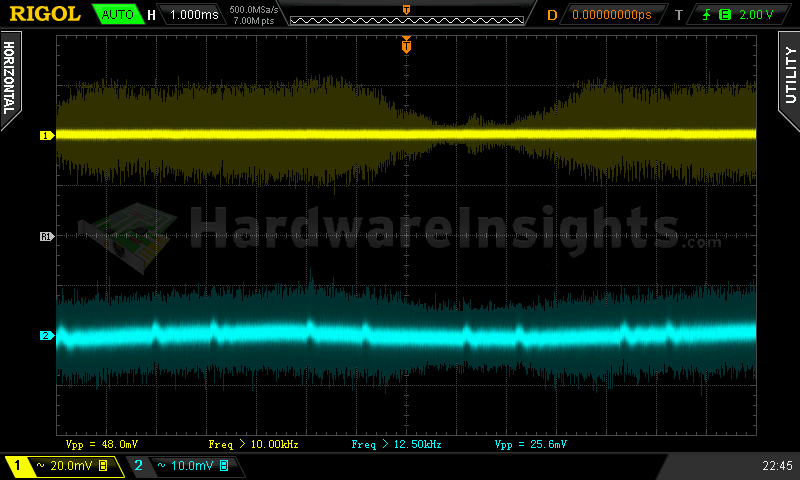
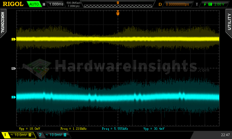
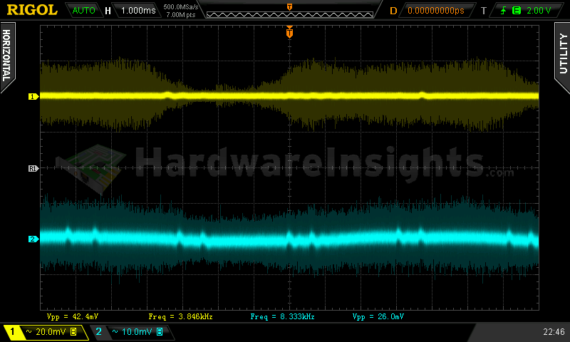
To check the result, I used test #5, and that is an 80% load. I used this particular test because the ripple was the highest here. With the changes applied, it was still pretty bad, but based on these results we can clearly see that it is now showing to be at least within spec. My suggestions based on this are to either add couple ceramic capacitors to each rail, or maybe couple polymers, those also work well with high frequencies.
