Introduction
Many power supply reviewers just build a powerful (and power-hungry) PC, connect the review subject to it and see how well it runs. Such reviews are a poor practice. They are not informative and often result in wrong conclusions. For this reason, we at Hardware Insights do not use this method. Instead, we have a purpose-built ATX power supply load tester (which we will talk more about later), as well as devices that measure the AC power draw, the power factor, the voltages and the ripple. This way, readers can see whether the unit they plan on buying can deliver the wattage stated on the label, and whether it could cause damage to the hardware it is connected to. Hardware Insights cover the following in power supply reviews:
– Load tests to determine what the power supply can deliver
– Voltage tests to determine how good the voltage regulation is
– Ripple tests to determine how clean the output is
– Efficiency and power draw tests to see how much power the unit wastes
– A dis-assembly of the power supply to determine what components are used and the build quality
In this article, we will discuss each of these.
The Load Tester
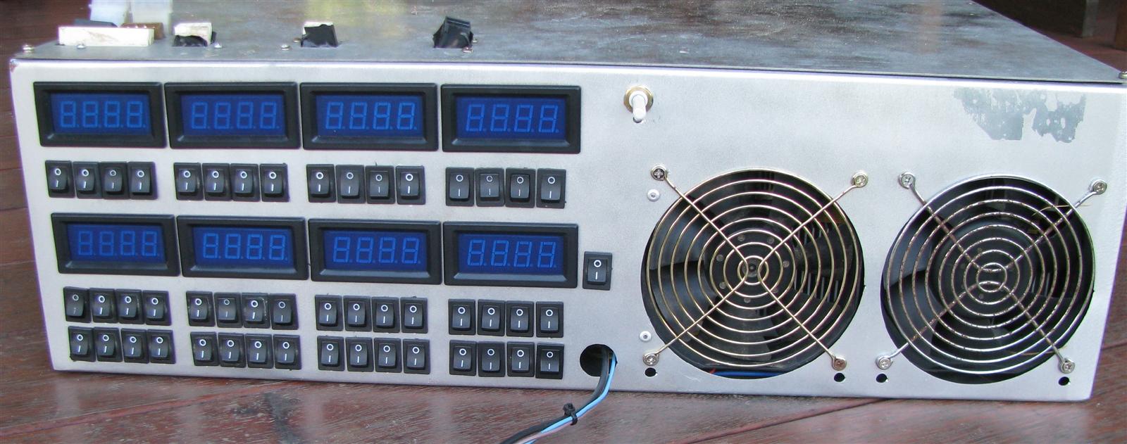
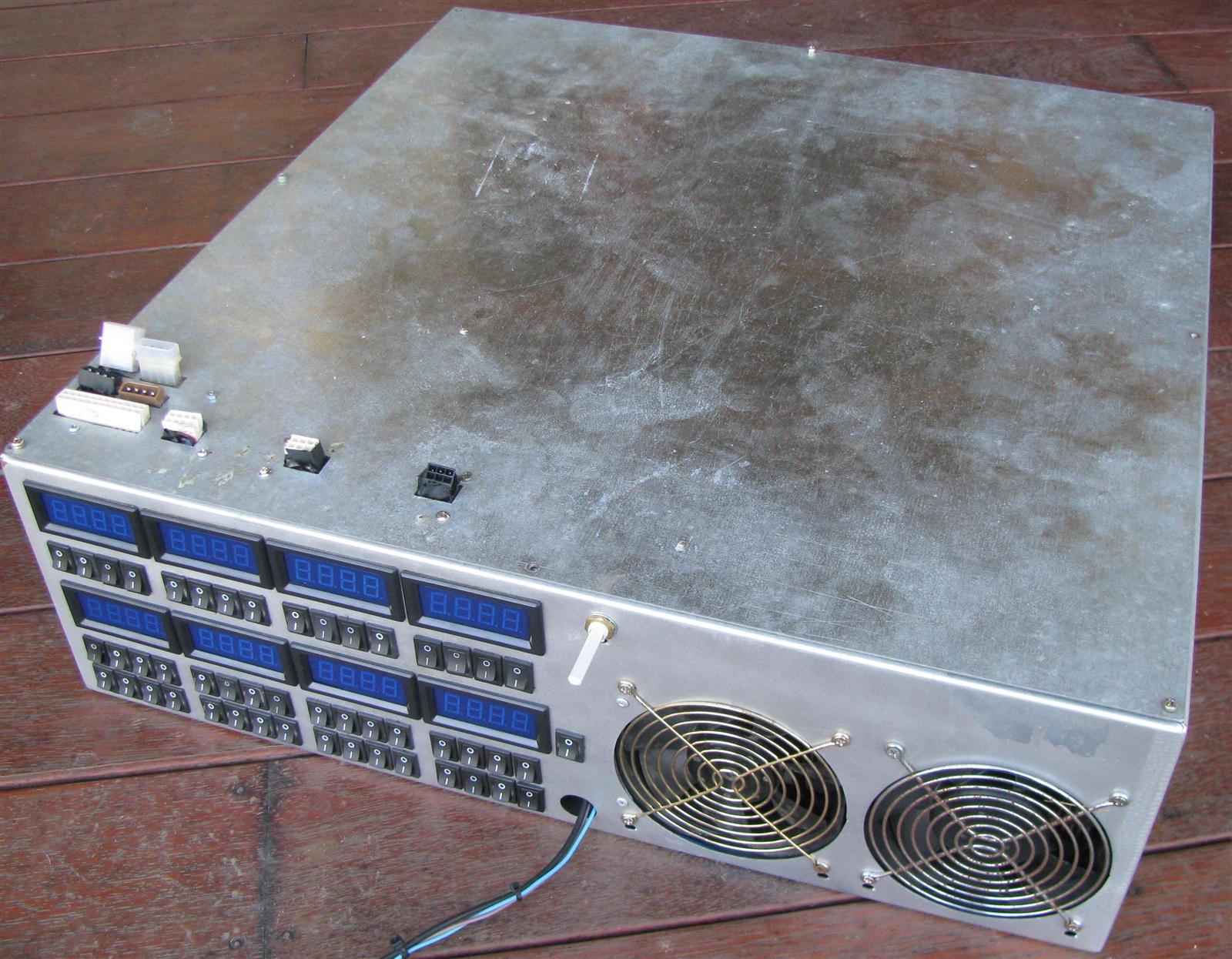
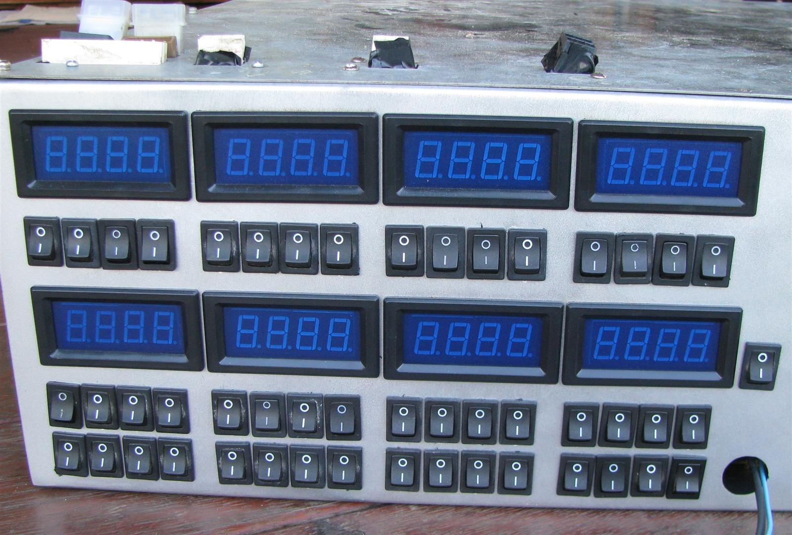
Our load tester is essentially a large bank of switchable resistors, housed in a custom-made case. Resistors are extremely easy to obtain and easy to set up. The drawback is that as they get hot, their power draw goes down. The workaround for this is to cool them well by having each of them mounted to a large heat sink with two powerful fans rated at 150CFM each mounted to the casing of the tester. Each of the resistors has a switch in series with it, which allows us to set the load on each rail by turning certain resistors on and off. The current loading capacity of our tester is about 1200W
We generally start at around 70W load for test 1 and increase the load by about 50-60W for subsequent tests, although using a resistor based load tester doesn’t always allow for us to go up by exactly 50W every time. If the test subject survives up to it’s labelled rating, we will the overload it until we find the maximum it can deliver. We consider the maximum to be what it can deliver without failing, shutting down, the voltages dropping below the minimum allowed in ATX specifications and/or the ripple going higher than the maximum allowed on any of the rails. Of course, if the unit is unable to deliver it’s labelled rating, it isn’t necessarily to be avoided. It may be the case that a unit labelled at 600W is unable to deliver 600W, but performs very well at 500W. It could still be an option for a user looking for a good 500W unit.
In the process of load testing the PSU, we automatically test for OPP and OCP (for more information on OPP and OCP, read our article on how a power supply works). If such protections are present and working, the power supply will shut down when we attempt to pull too much. If not, the power supply will fail.
_
DC Output Tests
There are two things we look for when testing the DC output of a power supply: the voltage and ripple. Poor voltage regulation and poor ripple suppression can both result in an unstable PC and even damage to the motherboard and/or other other hardware components.
The voltage is measured using an ISO-Tech IDM61 Digital Multimeter. While this meter is more expensive than the cheap $10 ones that some shops sell, it does offer much better accuracy, as some cheaper ones can be off by a fair bit.

The ripple is measured using a Hantek DSO-2090 USB PC-based oscilloscope. Ripple is essentially an oscillation in the output voltage of the power supply. It is measured in Peak to Peak Voltage (Vpp), or the difference between the maximum voltage and the minimum voltage. The ATX Specifications state that the ripple should not exceed 120mV on the +12v and -12V rails and 50mV on the other rails (+5v, +3.3v, +5vsb), although lower is always better. As a general rule, as the load on a given rail increases, so does the ripple.
Update: Shortly after we published this article, our Hantek oscilloscope was damaged. It has been retired and replaced with a USB Instruments/EasySYNC DS1M12 “Stingray” Oscilloscope


Power Draw and Power Factor Tests
All power supplies waste some power in the process of converting the mains AC into DC. The percentage of the power the unit is drawing from the mains that is actually delivered is the efficiency. For example, if a Power supply was being loaded to 300W, but was drawing 400W from the mains, the efficiency is 75%, since 75% of the power being drawn is what is actually being delivered. To measure the efficiency, we use a StepLight power draw meter, which is a re-badged Watts Clever EW5001. Watts Clever claim that it offers an accuracy of 0.05%, which is unusual on lower cost meters such as this one. We have found by comparing it with known loads that it is accurate to within 1%. Since we know what the PSU is delivering based on what load it is under, we can use it to calculate the efficiency. Below, you can see it measuring the power draw of a Topower built Global Win unit (similar to the one here) under very light load, only drawing 15.4W. It should be noted that reviews are conducted in Australia, where the mains voltage is 230v. This will result in a higher efficiency than if the power supply was running from 120v.

The power draw meter also has the ability to measure the power factor, which is what it appears to be drawing compared to what is is really drawing. It is presented as a decimal number between 0 and 1. For example, a device with a power factor of 0.5 is really only drawing 0.5 times (or half) what it appears to be drawing, so you will pay for twice the amount of power you really are using. Of course, the closer that number is to 1, the better. By nature, switching power supplies often have a low power factor. To improve the power factor, most half-decent power supplies have PFC (Power Factor Correction). The two methods are Active and Passive PFC. Active PFC (APFC) is generally much more effective and has the added advantage of correcting the input voltage as well, eliminating the need for an input voltage seclector switch at the back of the PSU.
The data from the tests is presented in tables. If a value in the voltage or ripple section of the table is coloured red, it is above the maximum allowed in ATX specifications. If it is blue, it is too low. If an entire table is red, it means that the power supply ran long enough to read the voltages, ripple and efficiency, but shut down or failed shortly after.
Dis-assembly and Build Quality Analysis
The last thing we do before moving on to the conclusions is open the test subject up and examine the build quality and what key components are used. By doing this, we can get an idea of how long the PSU might last by looking at the quality of the capacitors and fan, as well as determine the theoretical maximums of each rail by looking at the ratings on the transistors and rectifiers. If a unit fails during the test, a dis-assembly can also tell us what went wrong. Generally, we pull the unit apart enough to be able to tell what parts are used. If the unit is fairly open and we can read the part numbers on all of the key components without removing them, then we won’t disassemble it like we would a cramped unit where the part numbers on the transistors and rectifiers are covered over by other components. We feel that doing so would be a waste of time and solder.
Summary
Our testing method may not be the most advanced out there. However, we consider it be be more than good enough to educate potential buyers as to what they are purchasing, and we will continue to improve as more finances and equipment become available to us.