Contents
- 1Power supply testing instruments and methodology introduction
- 1.1History
- 1.2The Load Tester
- 1.3Power interrupter
- 1.4Future possible upgrades
- 2Other equipment
- 2.1Isolation transformer
- 2.2Anechoic chamber
- 3Measuring instruments (electrical values)
- 4Measuring instruments (non-electrical values)
- 4.1Measuring methodology/procedure
Measuring instruments (non-electrical values)
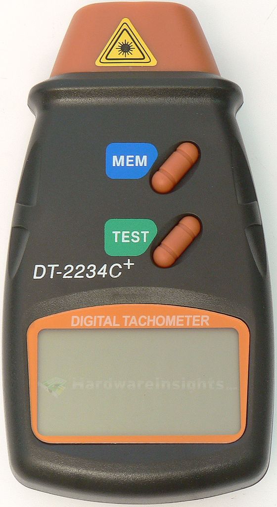
DT-2234C+ digital laser tachometer
- Used to measure fan speed
- Resolution of 0.1 RPM (2.5-999 RPM) or 1 RPM (1000-99999 RPM), however, as it always oscillates I state only whole RPM figures
- Accuracy of ±0.05 %+1 RPM
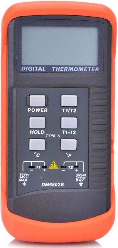
DM6802B dual-channel thermometer
- used for measuring temperature of the intake and outtake air
- range of -50 to 1300 °C, resolution of 1 °C (or 1 °F)
- accuracy of ±2.2 °C or ±0.75 % (whichever is greater)
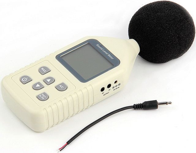
GM1358 sonometer
- used to measure noise
- range of 30-130 dBA, resolution of 0.01 dBA, accuracy of 1.5 dBA
- it is a cheap toy so the lower treshold is just a fantasy, never measures much under 39 dBA even in 100% silent room
Measuring methodology/procedure
All power supply units are measured on 230 V AC nominal input over 2 kVA separation transformer. This transformer can slightly lower the resulting voltage because of internal losses.
The measurement itself takes about 10-15 minutes for each load settings, with the exception of +5 V stand-by rail, where it is usually only tens of seconds (during this time, fans are not turned on, but the resistors heat extensively). The combined load is first set-up and only roughly measured, before everything heats up to constant temperature for constant load, I measure the ripple. Than I measure voltage, currents, power consumption, temperature and fan speed. Oscilloscope images are taken in native resolution using Rigol UltraVision Utilities.
When all the load tests are finished, the noise is measured in different place where we directly feed each units fan with voltage through external regulator. Thanks to this we can measure at known speeds (measured with tachometer during loading on the artificial load).
For simplicity, the results are first collected into a table and than commented on. In green, there are values which comply with ATX specification, in red those which do not. The absolute minimum for each power supply is zero red values (we can maybe tolerate ripple or voltage out of spec with no load, but even that should not happen for good power supply). If a unit does not comply with ATX spec, it should not even be on the market. The power figure in percentage is only reference, the actual computed value of output power according to load tester steps is important.
To create some reference efficiency-wise, I select testing in several load settings, approximately equivalent to 20 %, 40 %, 60 %, 80 % and 100 % of rated power, combined. Then, if possible, I will attempt to overload the units and see if protections are working. Cross-loading tests are also performed, loading one rail heavily and observing whether the others stay within ATX spec.
The ATX specification itself specifies voltage regulation within ±5 % for the + rails and ±10 % for the − ones, that translates into:
- 3.135-3.465 V for the 3.3V rail
- 4.75-5.25 V for the 5V and 5VSB rails
- 11.4-12.6 V for the 12V rail
- −13.2 V to −10.8 V for the −12V rail
The ripple and electrical noise than have to be at or under 50 mV for 3.3V, 5V, and 5VSB rails and a 120 mV for the 12V and −12V (peak to peak figures).
As for the hold-up time, ATX actually specifies two different hold-up times: voltage hold-up time and Power Good (PG) signal hold-up time. The first is 17 ms, the second is 16 ms. All of them must stay within voltage specification for at least the minimum time. I first decided to measure only the voltage hold-up time on the +12 V rail as it is the most important rail these days, other rails only provide negligible power in modern computer. And the Power Good signal may be interrutped later, when other rails fall from specification and the secondary monitor decides to wake up. But the ATX dictates the PG signal to drop first, followed by voltage HUT. Many units do not comply with that, on the other hand it is (usually) still no tragedy. Later I also started measuring PG hold-up time as often there are significant differences between these two.


