Model variance and what went wrong?
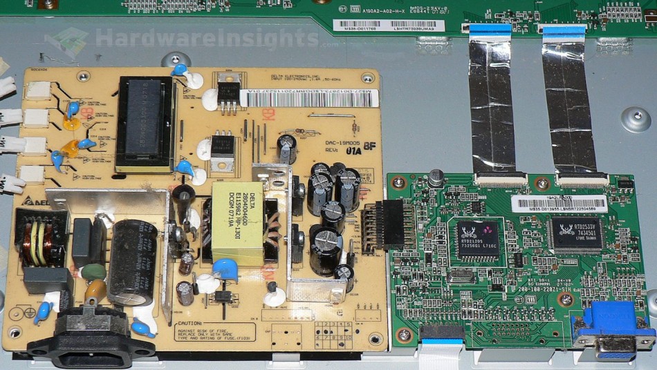
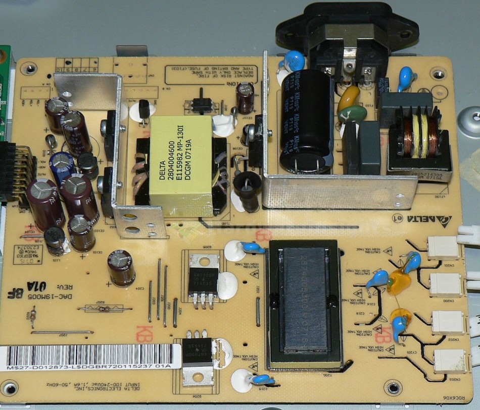
So we are finally inside. Clearly it is very similar to the original second version. It has the same display panel, the same logic board, and an almost identical power supply board made by FSP Group. The main difference however is that it uses different switchers in the inverter area – instead of two DIP-8 dual transistors (which almost burned through the board in the previous one) here we have two TO-220 transistors bent over to sit flat on the PCB.
Other than that we also have the same single primary switcher transistor and two output rails (+5 V and +13.5 V or so). Being an FSP branded board, they unfortunately chose their usual brand of C(r)apXon c(r)apacitors. Two of them in the inverter area are already bulging so we are going to replace all of them.
All of the caps were replaced with quality parts from my stock. Much, much better. But that in itself didn’t solve the problem, upon applying power again to the screen, there’s still no backlight! I wondered what could be causing it, considering that the transistors survived (you can see in the picture that I removed one but it actually tested good). I did however discover that the fuse tested open, which was probably caused by current spikes.
I did not have any 4A (or was if 3.5 A?) SMD fuses at the time, so as you can see, I soldered a 4A picofuse on the bottom of the board, solder side. Luckily, the wide tracks gave me ample room to solder it on. After I replaced the fuse, the display worked like a charm.
Discussion
Pages: 1 2


