Looking inside
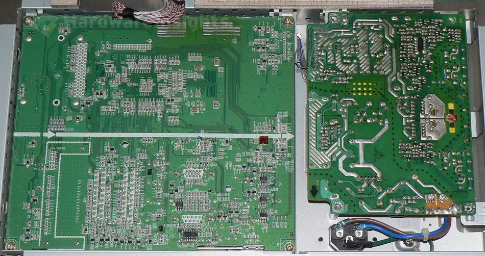
After we disconnect the LVDS cable from display and the CCFL tubes from the inverter, we can remove the metal cover that has the boards screwed in. There’s the large logic board with all the tuners, scalers, signal processors as well as the power supply and inverter.
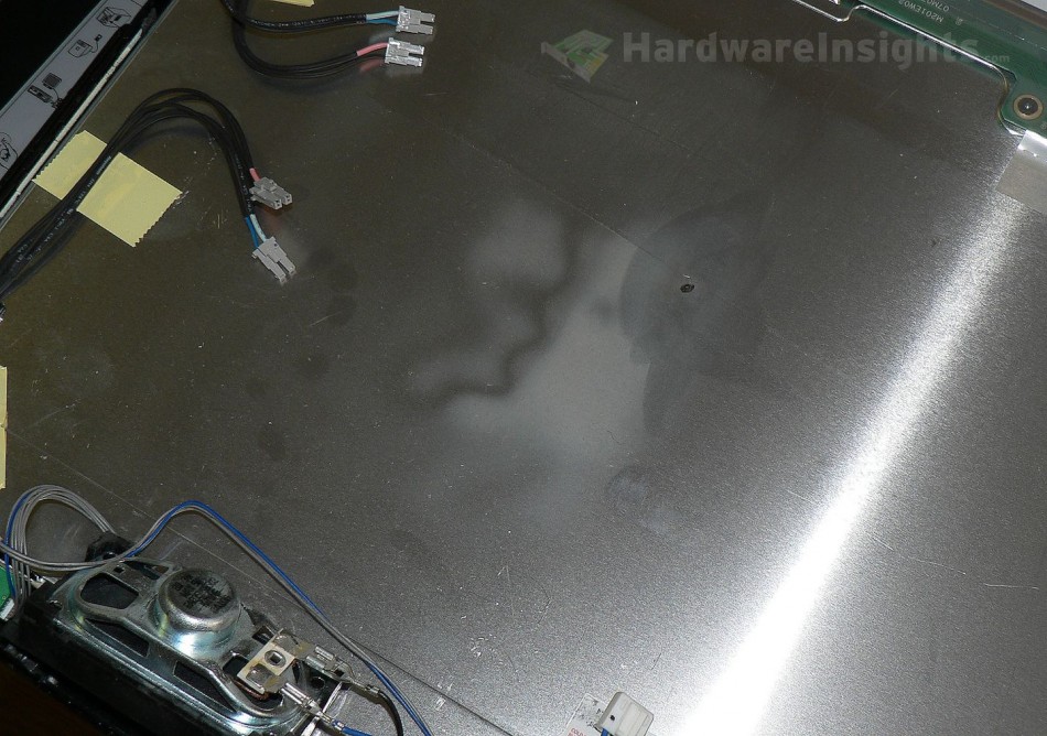
Woops! Whats this? A burned spot! Here’s a symptom of it supposedly tripping circuit breakers that I mentioned earlier. I’m not absolutely certain of the actual cause, but I have the feeling it’s a Y capacitor, perhaps that one between the primary and secondary side. But it may very well have been something else.
The important thing here is that the display was fully working even with that burned spot, and all it needed was a new input fuse. For some reason however, a short occured between some component leg and the metal plate on the display (which is earth grounded). If there was an insulating foil, this would have never happened. To prevent another short in the future, I cleaned the area and insulated it with some tape.
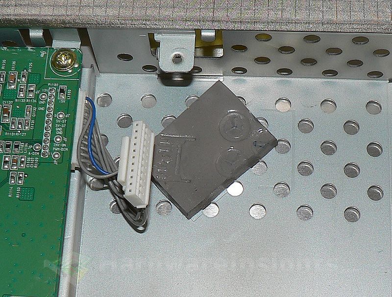
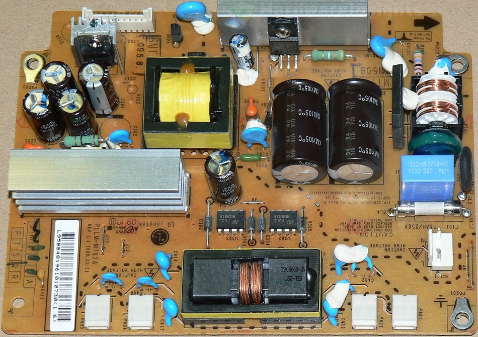
Removing the board is somewhat tricky as there is only a very short cable in a confined space between the boards which you need to unplug on both sides. As we can see, it uses an ordinary design with a PWM IC and integrated transistor, and there are two output rails. Overall it is quite similar to Samsung models.
Here we see the capacitors LG chose were all Sam Young brand (which is LG’s usual choice). They are not among the quality brands, so as I already had the monitor open, I went ahead and replaced them with quality Japanese (mostly Nippon Chemi-Con) caps from my stock, because the SamYoung capacitors would have failed prematurely.
Discussion
Pages: 1 2


