Contents
- 1Introduction
- 1.1Packaging and accessories
- 2Connectors & cabling
- 2.1Case & fan
- 3Input filtering
- 4Primary side
- 4.1+5 V stand-by rail
- 5Secondary side
- 5.1Build quality
- 6Load testing
- 6.1Loading +5 V SB
- 6.2Voltage hold-up time
- 6.3Combined loading
- 6.4Combined loading ripple
- 6.5Crossloading, overloading
- 6.6Crossloading, overloading ripple
- 7Conclusion and evaluation
- 7.1Thanks
- 7.2Discussion
Primary side
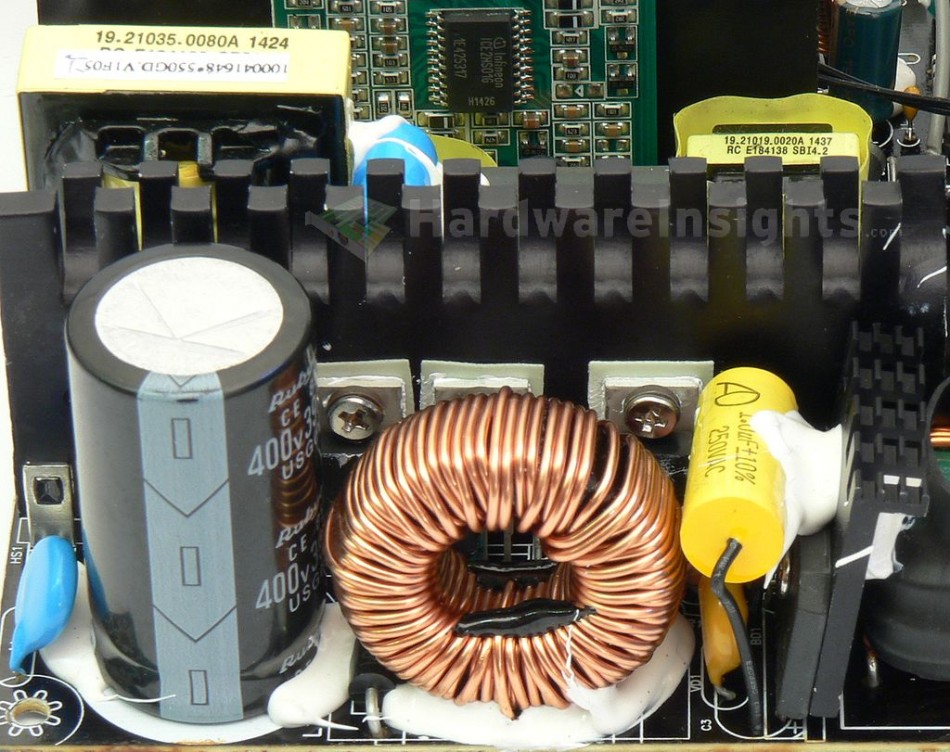
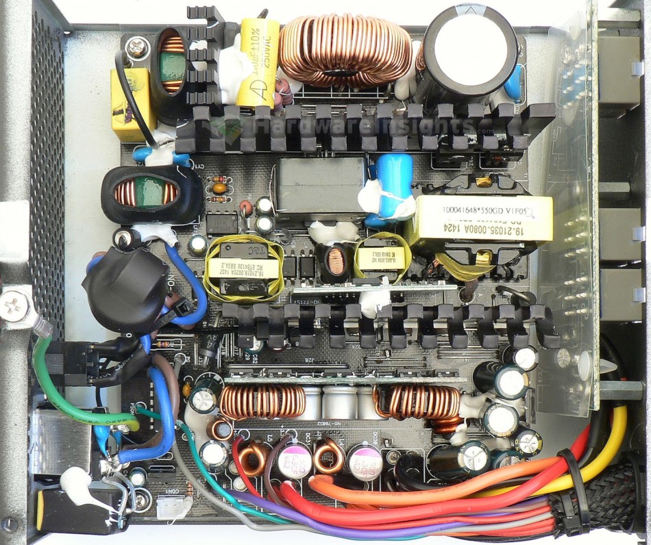
The primary side is basically same as in the Strider Gold S. It begins, as always, with a bridge rectifier, the GBU1006. It handles a current of 10 A continuously/220 A surge (for 8.3 ms) at 800 V and 100 °C. The voltage drop is 1.1 V per diode (at 10 A). The rectifier also has its own small heatsink with some fins, and the metal is a black-coated aluminium. The transistors in the PFC (boost-type) circuit are also Infineon branded, but they’re the somewhat inferior IPP50R250CE (13/31 A at 25 °C and 550 V, on resistance (Rds(On)) is 250 mΩ at 7.8 A and 25°C, 0.54 Ω at 150 °C) in a TO-220 package. The power diode in the PFC is an Infineon IDH06G65C5 (6 A continuously at 650 V and 145 °C, 48 A pulsed at 150 °C, voltage drop of 2.1 V at 6 A and 150 °C) in a TO-220AC package. The PFC coil is adequately sized with a sufficiently thick copper winding. The components here are over-spec’d, but only just about to my liking, that means to say, even higher-rated components certainly wouldn’t have hurt.
The capacitor charged by the PFC circuit is a Rubycon USG 390 μF/400 V (measures 344 μF) and rated at 85 °C . While a 420V and 105°C part would have been preferred, it is at least a 3000 hour 85 °C part (whereas most 85 °C capacitors are rated for only 2000 hours). The switching transistors are two IPA50R280CE (13/42.9 A at 25 °C and 500 V, Rds(On) 280 mΩ at 4.2 A and 25 °C, 660 mΩ at 150 °C), mounted on the other side of the common primary black heatsink in half-bridge configuration. The PFC circuitry is driven by an Infineon ICE3PCS01G controller located on the bottom side of the PCB. The switching transistors than by ICE2HS01G resonant LLC controller. This one is on a small daughterboard located on the secondary side, in front of its heatsink. The supply for the PFC controller is filtered by one Teapo SC 10uF/50V capacitor, and another 22uF/50V for the feedback. The main transformer has 35mm wide core. I must say that this unit is not looking like it’s off to a very good start.
+5 V stand-by rail
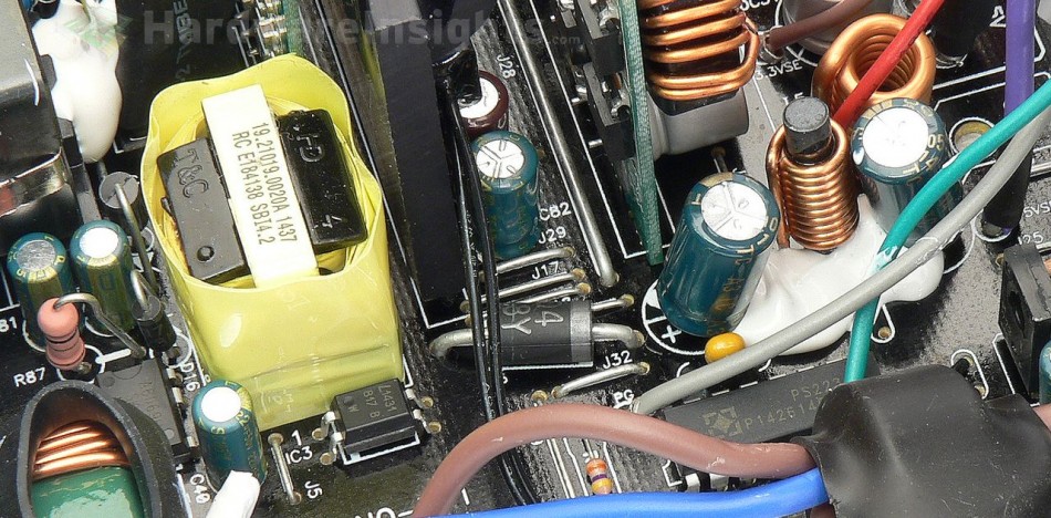
The stand-by rail uses the Sanken Electric STR-A6069H PWM controller with an integrated transistor rated for 700 V. It is rated only for 10 W while the unit’s specification claims 15 W output power, so I’m curious as to how it will perform. Its supply rail is filtered by another Teapo SC 22uF/50V (aieee)…
Behind the 20mm transformer is a single rectifying diode in a DO package and a filter consisting of two Teapo SC 1000uF/10V capacitors. This is going to fail hard under high load. Poor SilentiumPC with that five-year warranty should have used quality caps at least for the stand-by supply, that is my requirement for mainstream, let alone high-end units!


