Contents
- 1Introduction
- 1.1Packaging and accessories
- 2Connectors & cabling
- 2.1Case & fan
- 3Input filtering
- 4Primary side
- 4.1+5 V stand-by rail
- 5Secondary side
- 5.1Build quality
- 6Load testing
- 6.1Loading +5 V SB
- 6.2Voltage hold-up time
- 6.3Combined loading
- 6.4Combined loading ripple
- 6.5Crossloading, overloading
- 6.6Crossloading, overloading ripple
- 7Conclusion and evaluation
- 7.1Thanks
- 7.2Discussion
Secondary side
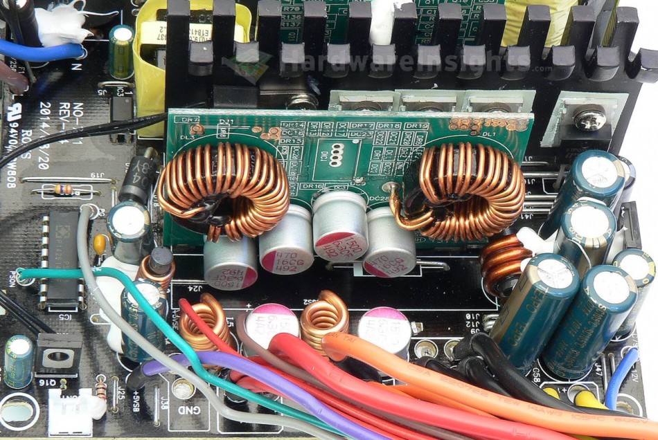
The active (synchronous) rectification here is handled by two pairs of some no-name transistors, possibly from InPower Semiconductor Corporation, the FTP03N04N in a TO-220 package. I have only found that they’re rated up to 196 A (pulsed I guess) at 40 V and the maximum drain-source resistance is supposed to be 3 mΩ, no datasheet. They are all mounted on the common secondary heatsink. The output is filtered by two Teapo SC 2200/16 caps before Pi coil and two more after Pi coil. Where is that vomitting emoticon?
Both the DC-DC modules are housed on a single daughterboard with an Anpec APW7159 buck PWM controller driving two pairs of Infineon IPD060N03L G (50/350 A at 25 °C and 30 V, Rds(On) 9 mΩ at 30 A and 4.5 V Vgs) transistors in a TO-252-3 package per each module (8 transistors together). The modules have a single 470/16 Teapo CG polymer capacitor for the extra +12 V filtering, and a 1500uF/6.3v part for the output directly on the daughterboard, with one more per rail on the mainboard (after the Pi coil). The −12 V rail has a single Teapo ST 470uF/25V part for the lower voltage feeding the KIA7912PI regulator and a Teapo SC 1000/16 for the filtering of the higher output. The Strider Gold S didn’t have good voltage regulation on this rail despite having a regulator, so I don’t expect too good of a result here either.
As this unit is semi modular, part of the power is conducted with a few 14AWG wires to another board holding the connectors. Unlike in the Strider, there are no extra filtering capacitors. A Silicon Touch Technology chip, the familiar PS223, is used for UVP, OVP, OTP, some OCP and also for generating a Power Good signa/turning on the unit. The thermistor for fan speed control and OTP is firmly screwed to the secondary heatsink while the HT772 PNP transistor in a TO-126 package is used for fan regulation (it’s an ordinary linear regulator).
Build quality
As usual I will focus on the overall build quality and other things like electrical safety here, as I’ve already discussed the quality of the components. A thermistor is not present at all, the varistor isn’t sleeved despite being sandwiched between components, and that’s not good. However, the filtering coils are insulated with heatshrink. Otherwise, there is sufficient clearance between all the other components. The prrimary and secondary side clearance is good, and as well, there are holes drilled under the main transformer for extra heat dissipation. Almost all the leads look professionally trimmed. The entire DC-DC module was soldered by hand on to the main board, as well as the AC input cables and the stand-by transformer. Unfortunately, the hand soldering is messy, and the flux residue was not cleaned off.
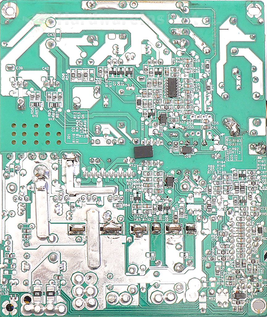
Due to the hand soldering of some of the components, I found about 20 solder balls and fragments all over the board. And they even neglected to put solder on a part of the copper layer towards the very top (image above). I must say, this really is very messy, and clearly Sirtec doesn’t care about these high-end units as long as they function, if even only somewhat. There are however some nice, thick conducting paths, but this only seems to amplify the problems, so I think 22 points should be at least the very minimum I should deduct from this unit’s score here. The modular board is nice and clean though, so I ask myself, why not the main board too?


