Contents
- 1Introduction
- 1.1Packaging and accessories
- 2Connectors & cabling
- 2.1Casing & cooling
- 3Input filtering
- 4Primary side
- 4.1+5 V stand-by rail
- 5Secondary side
- 5.1Build quality
- 6Load testing
- 6.1Loading +5 V SB
- 6.2Combined loading
- 6.3Combined loading ripple
- 6.4Crossloading, overloading
- 6.5Crossloading, overloading ripple
- 7Conclusion and evaluation
- 7.1Thanks
Load testing
Loading +5 V SB
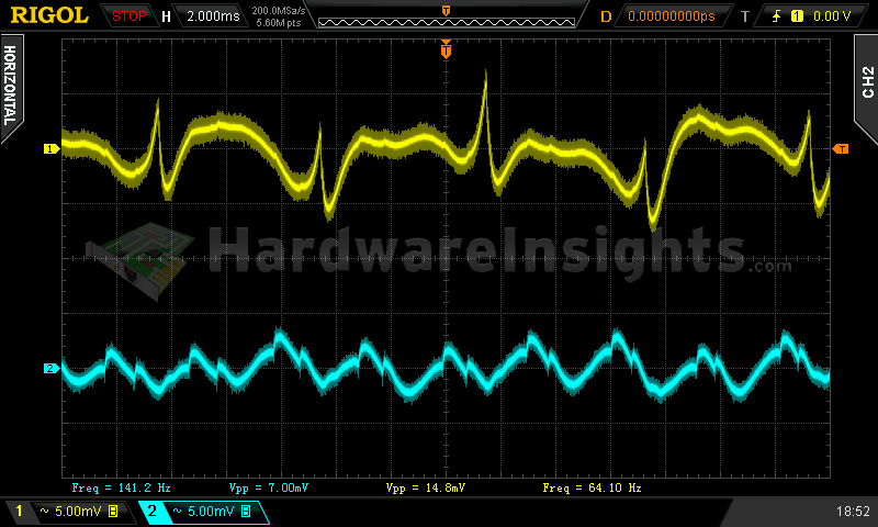
As always, all load testing is done in accordance with testing methodology. The stand-by supply in Silverstone Strider Gold S SST-ST55F-G(S) V2.0 had no problem providing both nominal power and extra power under (short) overload scenario. But using low-end PWM chip has its disadvantages – the voltage started very high so the supply does not drop below 5 V under load and the efficiency is barely 75 %. Ripple was great though.
| Output (W) | Load (A) | Voltage (V)/ ripple (mV) | Input (W) | Efficiency/power factor |
| 0 | 0 | 5.18/2.48 | 0.5 | —/1 |
| 14.88 | 2.93 | 5.08/1.68 | 20.0 | 74.4 %/0.41 |
| 17.24 | 3.40 | 5.07/2.08 | 23.0 | 75.0 %/0.43 |
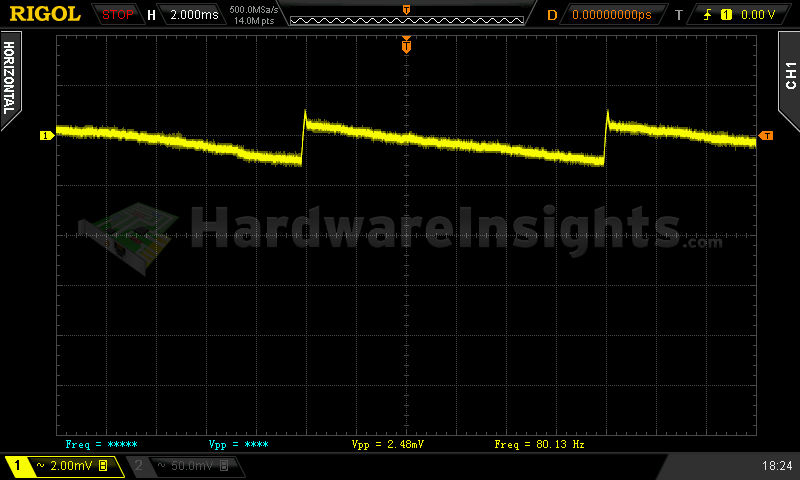
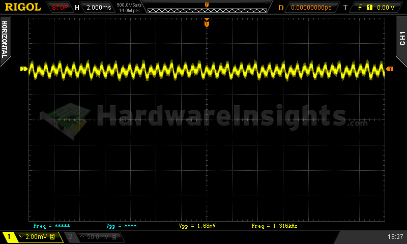
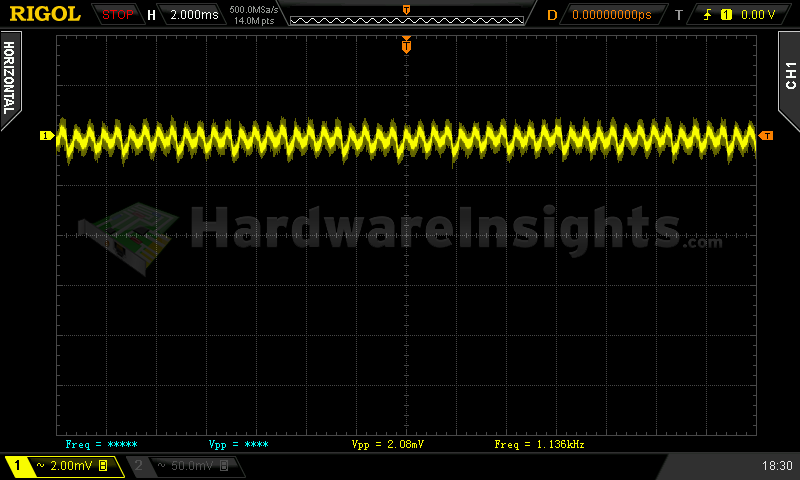
+5 V SB ripple (left to right): 0 A; 2.93 A; 3.40 A
Combined loading
Combined loading also went without major incidents. It seems that using cheap semiconductors takes its toll once again and despite having −12V regulator, the voltage regulation is as bad as without any regulator at all. Similar situation with +5 V, starting at 5.11 V and dropping below nominal by the end. But the stand-by rail won the race with 5.18 V no load, that’s 3.6 % over nominal value. Bad Sirtec, bad!
| Output power | Load/ voltage +5 V SB | Load/ voltage +3.3 V | Load/ voltage +5 V | Load/ voltage +12 V | Load/ voltage −12 V | Input power | Efficiency/power factor | Temperature intake/ outtake |
| 5.1 %/ 28.22 W | 0 A/ 5.18 V | 0.018 A/ 3.36 V | 0.297 A/ 5.11 V | 1.924 A/ 12.19 V | 0.293 A/ −11.11 V | 37.0 W | 76.3 %/ 0.73 | 26 °C/ 28 °C |
| 20 %/ 113.36 W | 0.504 A/ 5.15 V | 1.504 A/ 3.35 V | 1.502 A/ 5.08 V | 7.80 A/ 12.16 V | 0.290 A/ −11.21 V | 127.0 W | 89.3 %/ 0.97 | 26 °C/ 29 °C |
| 40 %/ 223.72 W | 0.99 A/ 5.12 V | 2.88 A/ 3.33 V | 3.36 A/ 5.05 V | 15.55 A/ 12.14 V | 0.291 A/ −11.42 V | 245.0 W | 91.3 %/ 1 | 27°C/ 32 °C |
| 60 %/ 330.2 W | 1.95 A/ 5.07 V | 4.26 A/ 3.31 V | 4.87 A/ 5.03 V | 23.0 A/ 12.10 V | 0.292 A/ −11.65 V | 358.0 W | 92.2 %/ 1 | 27 °C/ 36 °C |
|
80 %/ 436.82 W |
2.41 A/ 5.04 V | 5.92 A/ 3.29 V | 6.70 A/ 5.00 V | 30.5 A/ 12.07 V | 0.302 A/ −11.85 V | 476.5 W | 91.7 %/ 1 | 28 °C/ 37 °C |
| 100 %/ 550.82 W | 2.84 A/ 5.01 V | 7.18 A/ 3.27 V | 7.77 A/ 4.98 V | 39.1 A/ 12.04 V | 0.302 A/ −12.07 V | 610.5 W | 90.2 %/ 1 | 29 °C/ 40 °C |
Efficiency was OK with around 92 % maximum but low-load efficiency did not even reach 80 %. By the final test the unit’s fan was spinning on full speed (or close to it) yet it was slightly warmer anyway.
Combined loading ripple
I like what I see, I really do!! All the positive rail managed ripple less than 10 mV and even the −12 V rail with fan connected stayed within 20 mV. Finally, a result you would expect from high-end single-rail unit with active rectification and DC-DC modules.
| Output % | Ripple +5 V SB | Ripple +3.3 V | Ripple +5 V | Ripple +12 V | Ripple −12 V |
| 5.1 | 7.60 mV | 3.80 mV | 6.20 mV | 9.40 mV | 14.8 mV |
| 20 | 4.40 mV | 9.20 mV | 5.80 mV | 9.00 mV | 12.2 mV |
| 40 | 6.40 mV | 6.80 mV | 6.60 mV | 7.60 mV | 15.4 mV |
| 60 | 3.60 mV | 7.40 mV | 4.00 mV | 9.40 mV | 18.8 mV |
| 80 | 3.80 mV | 5.00 mV | 7.20 mV | 8.40 mV | 19.4 mV |
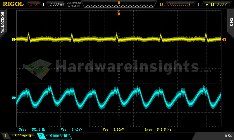
| 100 | 3.60 mV | 9.4 mV | 4.20 mV | 9.20 mV | 15.6 mV |
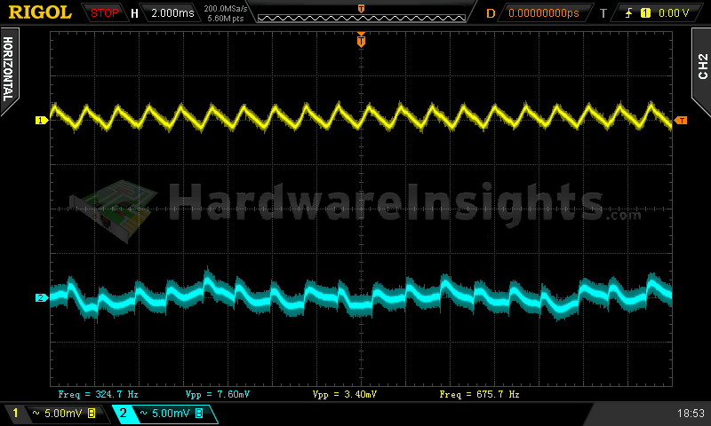
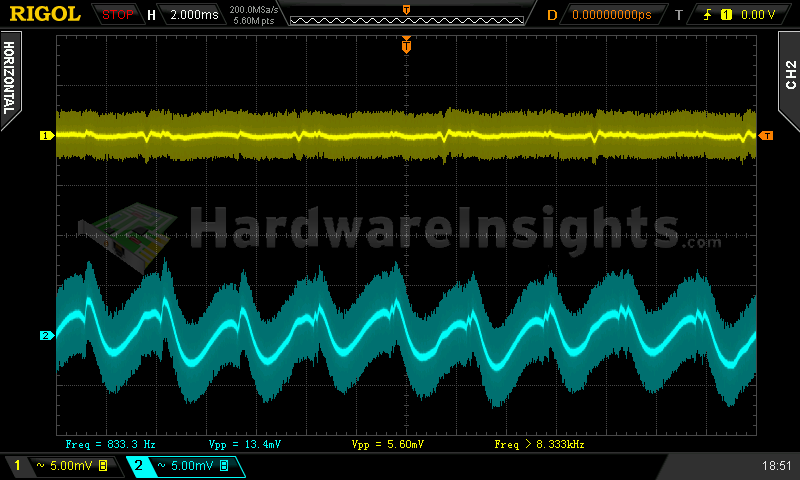
Ripple 5.1% load (left to right): +5 V SB; +3.3 V; +5 V; −12 V. The second channel is connected to +12 V.
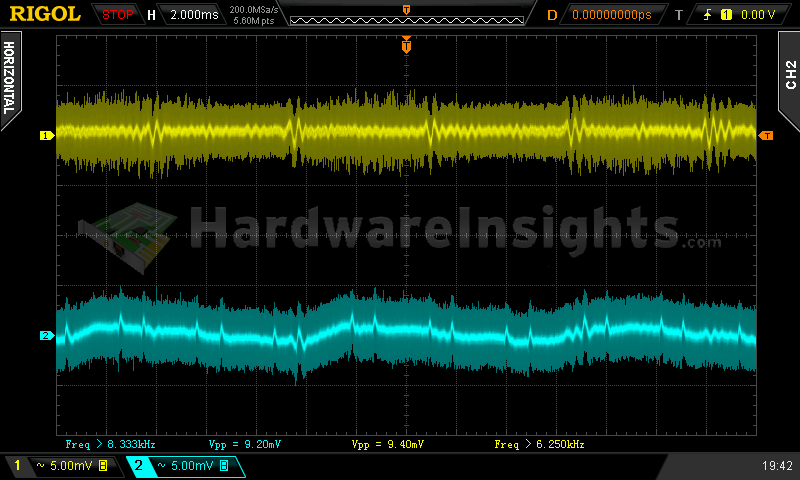
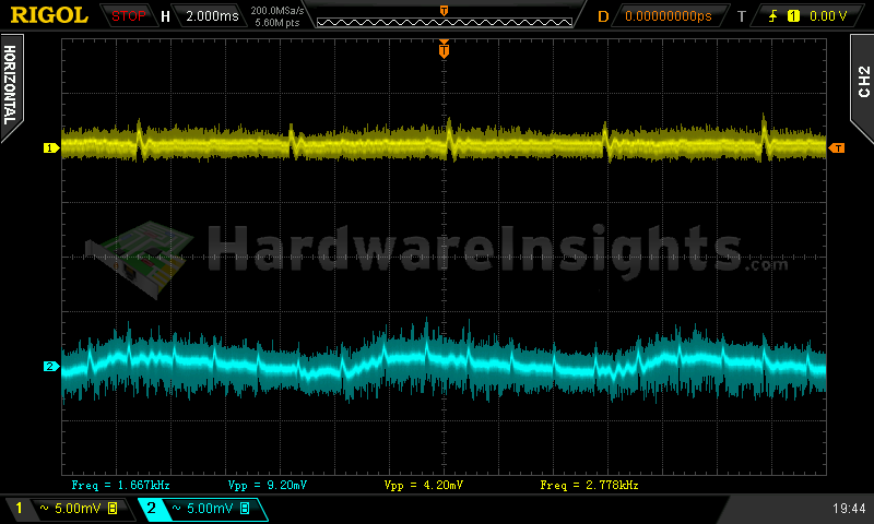
Ripple 100% load (left to right): +5 V SB; +3.3 V; +5 V; −12 V. The second channel is connected to +12 V.
Crossloading, overloading
Crossloading went quite well, considering this is +12V unit with DC-DC modules, I did not expect anything else. Voltage regulation was somewhat tighter, however, the stand-by supply still stayed quite high, out of 2 % regulation. OTP did not react as even with fan grille fully blocked by a sheet of paper, the unit was capable of cooling itself. OCP limit was not reached on any rail an all of them handled the applied overloading without any problems.
| Output power | Load/ voltage +5 V SB | Load/ voltage +3.3 V | Load/ voltage +5 V | Load/ voltage +12 V | Load/ voltage −12 V | Input power | Efficiency/power factor | Temperature intake/ outtake |
| 23 %/ 129.19 W | 0.499 A/ 5.13 V | 1.428 A/ 3.32 V | 19.23 A/ 4.98 V | 1.891 A/ 12.16 V | 0.278 A/ −11.26 V | 150.0 W | 86.1 %/ 0.96 | 27 °C/ 30 °C |
| 19 %/ 106,68 W | 0.498 A/ 5.13 V | 20.11 A/ 3.33 V | 2.21 A/ 5.05 V | 1.877 A/ 12.17 V | 0.279 A/ −11.25 V | 128.5 W | 83.0 %/ 0.97 | 27 °C/ 32 °C |
| 98 %/ 539.38 W | 0.494 A/ 5.09 V | 1.468 A/ 3.29 V | 1.193 A/ 5.03 V | 43.3 A/ 12.04 V | 0.300 A/ −12.06 V | 592.5 W | 91.1 %/ 1 | 27 °C/ 37 °C |
| 130 %/ 717.16 W | 3.30A/ 4.94 V | 8.56 A/ 3.25 V | 11.84 A/ 4.94 V | 50.9 A/ 12.00 V | 0.299 A/ −12.15 V | 810.5 W | 88.5 %/ 1 | 29 °C/ 47 °C |
Combined overloading finally triggered the over-power protection around 720 watt, that is approximately 30 % overload. Voltages dropped slightly but were still well within tolerance.
Crossloading, overloading ripple
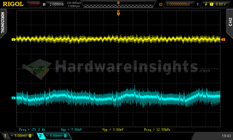
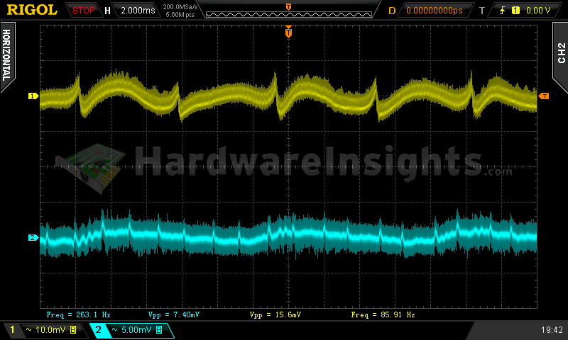
Under combined overload, the +12 V rail ripple finally exceeded 10 mV, but not by much, only to 11.2 mV. Still excellent results.
| Output % | Ripple +5 V SB | Ripple +3.3 V | Ripple +5 V | Ripple +12 V | Ripple −12 V |
| 23 | 4.80 mV | 6.00 mV | 7.00 mV | 9.60 mV | 15.2 mV |
| 19 | 3.40 mV | 7.80 mV | 3.60 mV | 5.00 mV | 13.8 mV |
| 98 | 4.20 mV | 5.80 mV | 9.00 mV | 9.80 mV | 16.6 mV |
| 130 | — | 6.00 mV | — | 11.20 mV | — |