Contents
- 1Introducing the Topower SilentEZ 350W
- 1.1Packaging and accessories
- 2Connectors & cabling
- 2.1Casing & cooling
- 3Input filtering
- 4Primary side
- 4.1+5 V stand-by rail
- 5Secondary side
- 5.1Build quality
- 6Load testing
- 6.1Loading +5 V SB
- 6.2Hold-up time
- 6.3Combined loading
- 6.4Combined loading ripple
- 6.5Crossloading, overloading
- 6.6Crossloading, overloading ripple
- 6.7Fan speed, temperatures and noise
- 7Conclusion and evaluation
- 7.1Thanks
- 7.2Discussion
Primary side
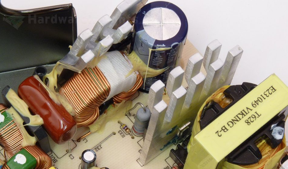
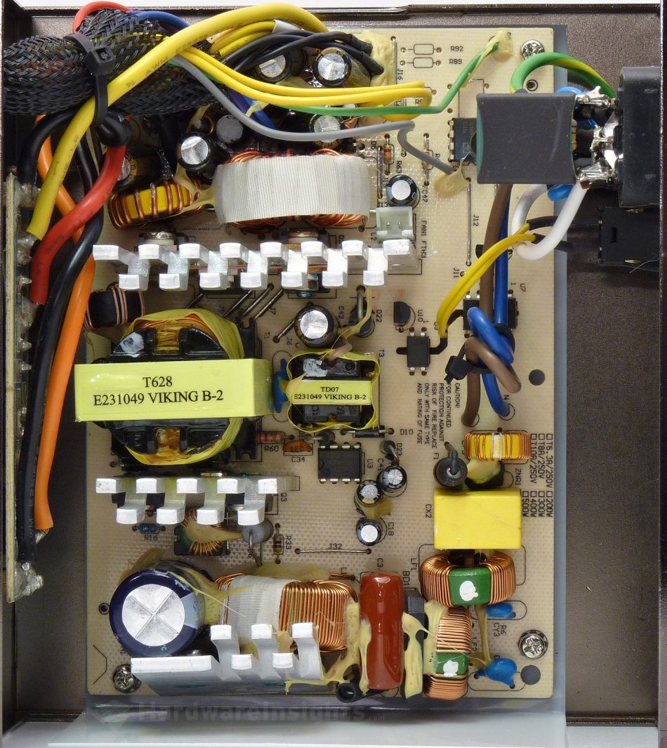
The primary side of the SilentEZ 350W starts with input bridge rectifier, the GBU606. As it does not carry a heatsink, it is limited to under 3 A continuously (175 A surge) at 100 °C. Maximum voltage is 600 V, voltage drop 1.0 V per diode. As the unit is 200–240V input only, this should be pretty much enough. The PFC silicon consists of a single STMicro STP9NK60ZFP (7/28 A at 600 V and 25 °C, RDS(On) 0.95 Ω at 3.5 A) transistor in TO-220FP package and STTH8R06D (8/30 A at 600 V and 130 °C, 2.9 V@8 A and 25 °C, 1.8 V @125 °C) power diode in TO-220AC package. These use separate aluminium heatsink. The PFC coil again uses quite thin wire for winding and the core is also not particularly large, but for the power @230V nominal this is OK.
The bulk capacitor is C(r)apXon GS 120 μF for 400 V, which measures at 112 μF. This capacity is way too low for any proper hold-up time, I think it is safe to say that right here, this unit will most likely fail. Plus this series is only general purpose capacitor with 2000 hours endurance at 85 °C. Did I also mention it is C(r)apXon? I wonder it survived for 9 years on shelf… The two switchers, again STP9NK60ZFP, use forward configuration and also have their own heatsink. The main transformer has 35mm core.
The PFC/PWM combo driver in the SilentEZ 350W is from Champion Micro, the CM6805BG. As usual, we can see lots of talk about advantages such as smaller bulk cap etc. However, I think the result in using just 120μF capacitor for 350W unit is more like Topower’s own initiative. After all, Champion Micro has 100μF capacitor for 90W power brick in their sample circuit… For filtering of the power supply line of the microchip a Hermei HT 22/50 capacitor is used.
+5 V stand-by rail
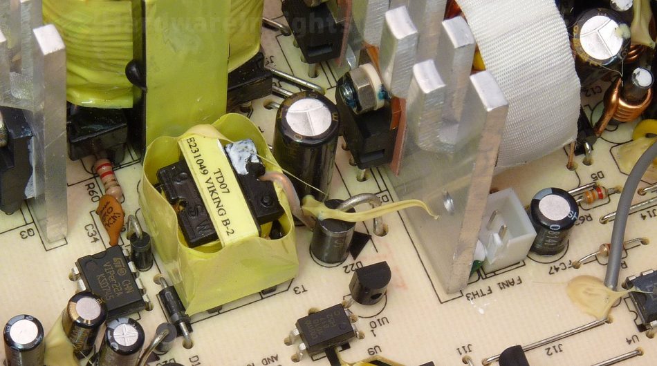
The stand-by rail uses PWM controller with integrated transistor, one of the first such ICs, the well-known VIPer22A from ST Micro. This microchip in the DIP-8 version can move 20 W of power so the rated 12.5 W should not be any problem. The integrated transistor however has quite high On resistance of 31 Ω at 100 °C. And indeed, the VIPer’s most problematic drawback, compared to more modern designs, is high losses under load. It should however still make the stand-by power supply more efficient and safe than the old self-oscillating two-transistor designs.
The power supply of the VIPer22A has one Toshin Kogyo 22/50 and one C(r)apXon 10/50, one better than the other…after the transformer with 15mm core, there is a Schottky diode for single-way rectification. There are two more Hermei caps in the Pi filter, LE 1000/16. Though I have only seen a few failed Hermei capacitors so I do not take this brand as total garbage, I still would not use it for any serious task. After all, it shares the same parent company (Kaimei) with Jamicon and Asiacon…


