Contents
- 1Introducing the Whitenergy ATX-350W
- 1.1Packaging and accessories
- 2Connectors & cabling
- 2.1Casing & cooling
- 3Input filtering
- 4Primary side
- 4.1+5 V stand-by rail
- 5Secondary side
- 5.1Build quality
- 6Load testing
- 6.1Loading +5 V SB
- 6.2Voltage hold-up time
- 6.3Combined loading
- 6.4Combined loading ripple
- 6.5Crossloading, overloading
- 6.6Crossloading, overloading ripple
- 6.7Fan speed, temperatures and noise
- 7Conclusion and evaluation
- 7.1Discussion
Primary side
Lets take a deep breath and dive into this river of…ATX-350W. First, this unit has discrete diode treatment! There is a position for bridge rectifier, however, as it is slightly cheaper, only 4 separate diodes are used instead. But the 4World could have saved half a cent more here yet they wasted the money! You may notice two of the diodes are “beefier”. That is intended for the 115 V AC input where only those two diodes are used; the remaining two are bypassed by a voltage-doubler switch. So these diodes are usually bigger as they have to carry more current. However, as this is 230 V AC (nominal) unit, all four diodes are used equally and the no-name maker could have made all of them smaller ![]() The diodes are RL257 (2.5/200 A at 1000 V) and 1N5408 (3/200 A at 1000 V).
The diodes are RL257 (2.5/200 A at 1000 V) and 1N5408 (3/200 A at 1000 V).
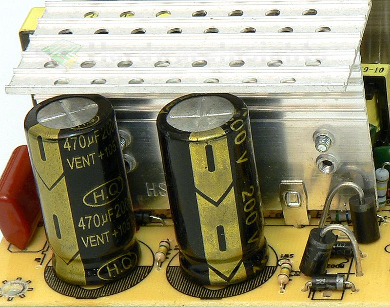
While there is a spot for connector from passive PFC coil, this unit has no power factor correction mechanism whatsoever. I have no ability to measure harmonics, but even from the power factor itself it will be pretty evident this unit has no chance of passing the international standard IEC 61000-3-2. And that does not apply only for the harmonics, but due to poor input filtering I doubt it will cope with any electromagnetic standard at all. The capacitors charged from the rectifier section are two H.Q 470 μF/200 V in series, which remained from the original platform embedding voltage doubler even though it is not present. I am not familiar with this generic “brand”, we can assume they are of the worst on the planet. Indeed, I have measured one at 202 μF and the other one at 230 μF, that is already more than 10% difference one from other and less than half the nominal capacitance!! That leaves us with just about 100 μF effective capacitance at 400 V!
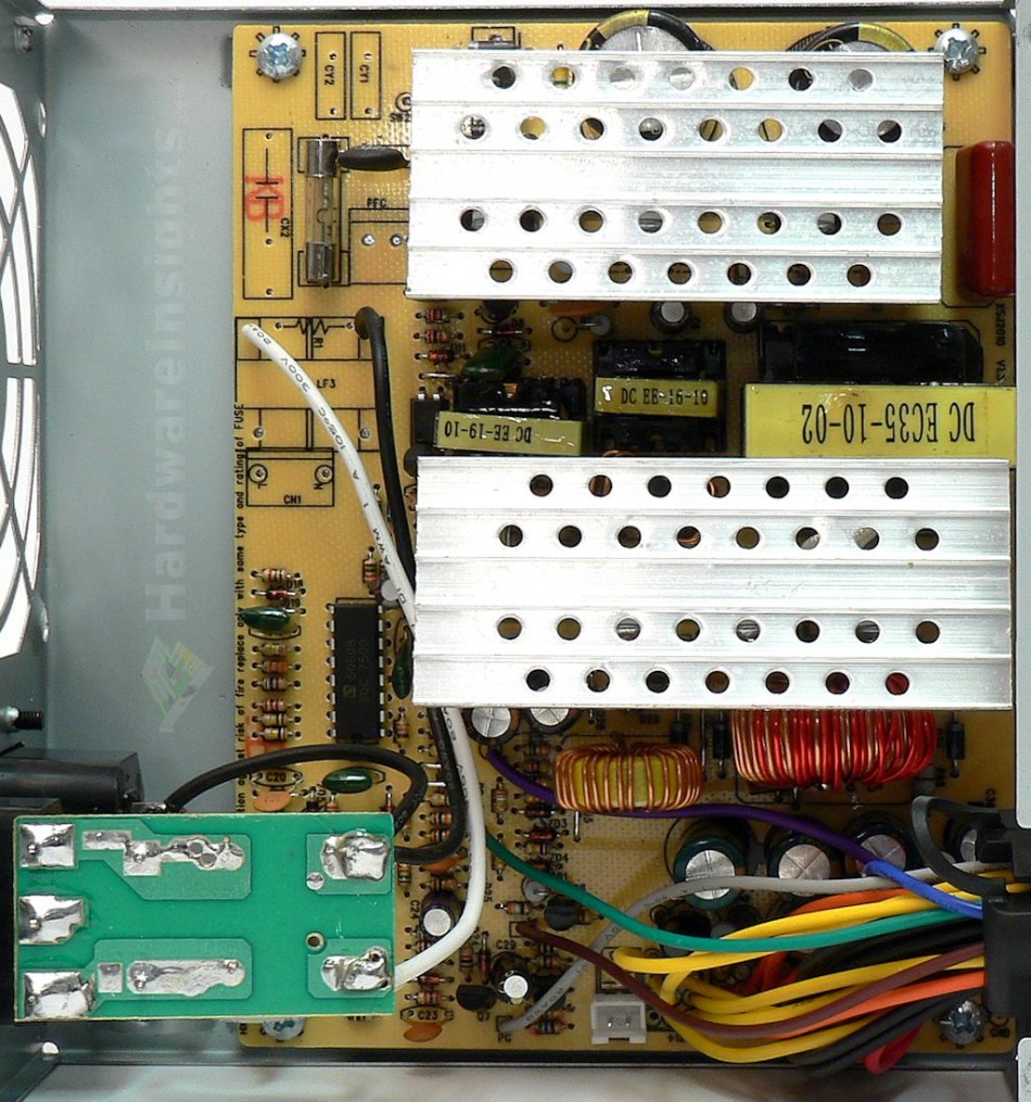
The platform is obviously still the same half-bridge from 1980s, using SDC 7500 aka KA7500 (aka TL494). As always combined with the famous 13007s, hit of the 1970s, in TO-220 package mounted on paper-thin heatsink. These NPN transistors can handle 8/16 A at 700 V. With the horrendous efficiency, capacitors in use and duty cycle, this gives us about 200 W, maybe 250 W for a while, we will see. The transformer in use is 35mm wide but it is rather short so 200 W will be more like it. While this unit seems like one from Leadman, it is more likely some no-name Chinese copy of that. That should give you the overall idea. The board says it is XSJ2010 V1.5 so we can assume this exact platform from this maker is in use since 2010 with just slight revisions.
+5 V stand-by rail
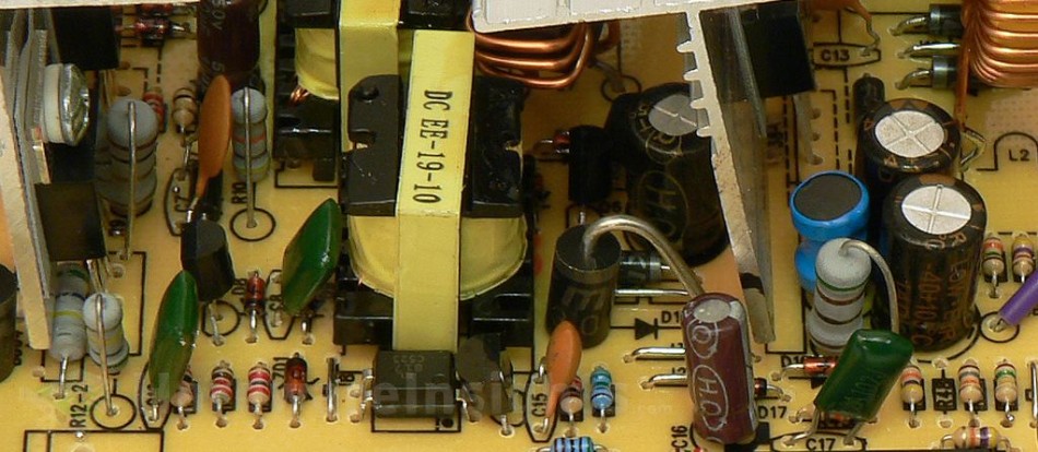
More terror. Two-transistor forward with more H.Q caps, including critical start-up cap. When it dies, your motherboard dies. I would thought these things finally died of with that new legislation, but this ATX-350W shows us the two-transistor does not give up! Because guess what…importers do not care! The transistors in use are RC3866 and 2SC1815. I have not found the datasheet for the first one but I think it does not matter anyway, the chance is we can only be more terrified, not surprised in pleasant manner. Transformer uses 19mm core.
There’s a diode in DO-201 package for single-way rectification and two 470/10 caps for filtering. It may be able to provide 1.5 A but the efficiency will be atrocious and the no-load power draw will be well over 0.5 W so this PoS will also not comply with European socialistic commission order 1275/2008 (1 W from 2010, 0.5 W from 2013). We’ll see…


