Contents
Introduction
The role of a power supply is convert the mains voltage into a lower DC voltage which the components can run on. There are two types of PSUs out there – linear and switching/switch-mode power supplies (or SMPSs).
Linear power supplies were the first power supplies used to convert high voltage AC into DC. They use a transformer which is connected directly to the incoming AC mains power. The lower voltage output, however is still AC. To convert it to DC, Diodes and Capacitors are used. Diodes allow the current to only flow in the right direction – converting the AC into pulsed DC, and capacitors then smooth out the resulting oscillations. The main disadvantage of linear power supplies is the low frequency AC which they have to work with (50 or 60Hz). This requires a very large and heavy transformer to be used, and they can be very inefficient (especially lower-power types with regulated outputs). For these reasons it is impractical to use them to power a computer. Instead, Switching power supplies are used.
Switching power supplies are more complex than linear power supplies, but they work on the same basic principles. We will take a more in depth look at how they work in this article.

A switchmode power supply consists of 8 main stages: The input filtering (green), primary bridge rectifier (dark blue), primary capacitors (yellow), primary switching transistors (red), transformers (orange), secondary rectifiers (light blue), output filtering (purple) and the feedback and protection circuits (black). In this article, we will look at each of them and discuss what they are for.
Input filtering
Switching power supplies generate substantial amounts of interference which, if not filtered out, is fed back into the mains power and can cause problems for other appliances which are connected. AM radios, for instance, are particularly susceptible. The main role of the input filtering is to reduce this interference.


The minimum recommended number of components for the input filtering are two coils, two ceramic Y capacitors – one installed between Active and Earth and the other between Neutral and Earth, two polyester or polypropylene X capacitors (which are installed between Active and Neutral), an NTC current inrush limiter and an MOV. The above left power supply (an Aywun A1-5000) includes more than enough X-capacitors, but lacks an MOV (which looks similar to a Ceramic Y-Capacitor, but is usually dull yellow in colour), whose job it is to eat up any spikes on the power line, so it’s unlikely that it would handle handle them too well. The one pictured to the right of it however (an NSCom P4-500W) doesn’t have any input filtering whatsoever, so it would not only be very susceptible to surges from the power grid, but would also cause a lot of interference. Such power supplies are illegal in many countries. While both X and Y capacitors are required for earthed power supplies such as PC power supplies, Y capacitors should not be used in double-insulated non-earthed power supplies (although they often are), as they can inject considerable amounts of interference into the grounding of connected equipment, or discharge into and damage delicate signal circuitry if interconnections (such as A/V leads) are plugged or unplugged with the power on.
A common problem with both ceramic and polyester capacitors is their usual failure mode. If they are overstressed by a power surge, they often short internally (as if a jumper wire was installed across their pins). This poses a risk to the user, as a shorted polyester can cause a fire if the breaker in the house does not trip, and a shorted ceramic capacitor can cause the casing to become live if the earth connection is lacking. For this reason, it is important to use X and Y class capacitors which are approved for use on mains power for input filtering, as they are designed to fail open (as if they weren’t installed) when they are overstressed, and are designed to be non-flammable. There are a few sub-classes within the X and Y class certifications – X1 and Y1 and X2 and Y2. X1 and Y1 capacitors are certified for higher voltages than X2 and Y2 capacitors. The latter are usually used in PC power supplies, since they are somewhat less expensive and are still certified for high enough voltages (although X1 and Y1 parts can be used as well).
A small resistor (or a series string of SMD resistors) is required in parallel with the X capacitors to discharge them after the AC is disconnected (otherwise the user could get a shock touching the plug/inlet pins). These resistor(s) will have a combined value between ≈200k and a few M ohms. Special integrated circuits (such as CAPZero) have been developed in recent years to switch the resistors in circuit when the AC is unplugged, while keeping them disconnected with the AC present – allowing lower-value resistors to be used for fast discharge, without wasting energy on keeping them warm while the AC is present.
MOVs (metal-oxide varistors) are used to suppress surges and spikes from the power line. Their main limitation, however, is that they degrade from the surges experienced, which causes their threshold voltage to drop with repeated use. Eventually, given enough surge action, the MOV will reach the point of conducting at the normal AC voltage, which will cause it to overheat and eventually burn (this may never happen in the life of the unit, or may take mere weeks, depending on how polluted the power line is). Alternatively, a single massive surge may instantaneously blow the MOV apart, leaving the PSU vulnerable. Despite these shortcomings, their advantage of being small (and cheap) for their energy absorption is such that they remain prevalent, and they are often adequate where the power in the area is reasonably clean. Larger MOVs are preferable as they can absorb more energy, and MOVs can survive exponentially larger numbers of weaker surge events (relative to the MOV’s rating). A PSU will usually have either one MOV across the AC input (before or after the EMI filter – it doesn’t really matter either way), or in older non-APFC units, two lower-voltage MOVs, one across each of the two primary capacitors (more on them later).
The fuse, while not considered as part of the input filtering, is often located in that area of the PCB. Its job is not to filter surges and interference, but to blow should something go seriously wrong such as one of the components failing shorted, preventing the shorted part from causing a fire.
The NTC thermistor is there to limit the amount of current a power supply can pull when the primary capacitors initially charge. It is essentially a resistor whose value drops at high temperatures, which allows it to do its job when the power supply is initially connected to the mains and thus is cold, but without wasting too much power when the power supply has warmed up. Some power supplies include a relay, which is an electrically operated switch, to bypass it once the primary capacitors have charged, which improves the efficiency further (and also enables a higher-value NTC to be used, further reducing the inrush).
The bridge rectifier
This part converts the AC current from the mains into a pulsed, non-continuous DC – much like the rectifiers on the low voltage side of a linear power supply, although the primary side rectifiers are rated for a much higher voltage (typically 600V, although 400V will function but is marginal). The current rating of the rectifier will not have a huge effect on the performance of the PSU, but it does determine the maximum amount of current that the power supply can draw from the mains – too much and the rectifier can overheat and short. In most decent power supplies, a single part is used with the four diodes integrated into it. Some cheaper power supplies, including many of the units we test in the el-cheapo PSU roundups, use four individual diodes. They function the same way, but they typically have much lower ratings (usually no more than 3A). (Some cheap non-APFC units even use two pairs of different sized diodes – in those arrangements, the two larger diodes are those active when voltage-doubling, where the higher current rating is necessary, while the smaller diodes are used in the half of the bridge only required with 200–240VAC input, which get to ‘rest’ in voltage-doubling mode. More on the voltage doubler in a bit.)
To get an idea of how much the rectifier can handle, find its rating, multiply it by the mains voltage and multiply that by the PSU’s efficiency (which is typically around 75% for a cheaper unit on a 120v mains voltage), then de-rate by 20% if the supply lacks Active PFC. For example, if the rectifier is rated at 4A and the mains voltage is 120v, then 480W (4 x 120) is the maximum the PSU can draw from the mains and 360W (480 x 75%) would be the maximum theoretical output if the efficiency was 75%, assuming that the other components can handle it.
Bridge rectifiers may or may not be attached to a heatsink. Sometimes, they are only rated for what they can pass with a heatsink attached. Excluding a heatsink with such a rectifier would reduce its capacity.
Some recent ultra-high efficiency designs actually forego the bridge, using alternative arrangements to avoid the voltage drop the bridge adds (typically about 1V per diode, so ≈2V overall given that two of the diodes are in the current path at a time).
The primary capacitors
These smooth the pulsed DC current coming from the rectifier into a smooth, constant DC for the primary switchers to work with (similar to the secondary side capacitors in a linear power supply). In power supplies with Active Power Factor Correction (more on that shortly), there is only one capacitor, usually rated for 400 to 450V. Two (or more) are sometimes used in parallel if a high capacitance is required. Other power supplies have two 200V parts. In a 120v power line, they are used in voltage doubler mode, where they are charged in parallel and discharged in series, so the output voltage is double the voltage coming from the rectifier (which in turn is typically about 1.4 times the incoming AC voltage).
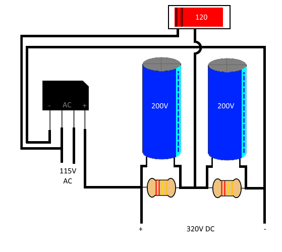
When set to 230V, the capacitors both charge and discharge in series, giving an output voltage of 322V DC. With the switch closed, one side of the incoming AC is connected to the mid-point between the caps. This charges one of the caps during the positive half-cycle and the other on the negative half cycle. If the input voltage is 115V, each capacitor is charged with about 161V, giving the same 322V then they are discharged in series. There are normally two resistors added to allow charge to flow between the capacitors – maintaining equal voltages across both. These are referred to as bleed resistors. The absolute value of these resistors is not critical (but both resistors should be the same). A lower value allows more charge to flow between the capacitors, but wastes more power. Values of between 100k and 1M ohms are typically used.
This role is not generally particularly stressful for a capacitor, and so even parts from lower quality manufacturers often hold up OK in this part of a power supply.
Power Factor Correction
Not all loads are easy on the power grid. Resistive loads such as heating elements and incandescent light bulbs only pull the amount of current they need to do their job. Devices such as SMPSs, however, are not inherently so graceful. They heat the wires and put more pressure on the grid than their actual power consumption would suggest. This discrepancy is referred to as the Power Factor. It occurs when devices either draw current out of phase with the voltage cycle (as is common with AC induction motors and old-style inductive ballasts for discharge lighting) or, as in the case of SMPSs, only draw current right at the peak of the AC cycle (which is worse still as it also distorts the AC waveform).
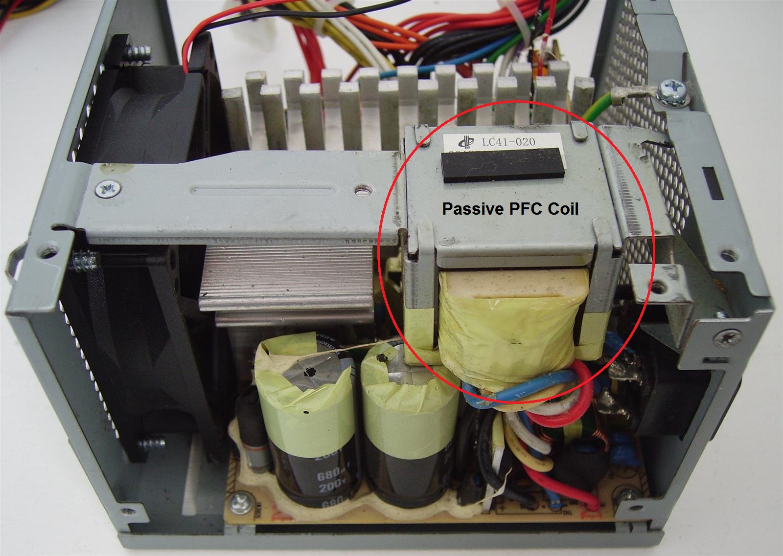
Most power supplies with no PFC have a Power Factor value of about 0.6 – meaning that the power supply is actually using 0.6 times it’s apparent power (ie, the load that it is putting on the wires and grid). A simple way to improve the power factor is to add a large inductor (sometimes with a small film capacitor in parallel with it) in series with the primary capacitors, either before or after the bridge rectifier, which smooths out the current pulses somewhat. This approach is known as Passive Power Factor Correction. It typically brings the power factor up to around 0.75, much like we saw on the Dell H305P-01 pictured above. While a significant improvement over the uncorrected power factor, with the improved performance and reduced cost of Active PFC (next paragraph) it is now all but obsolete.
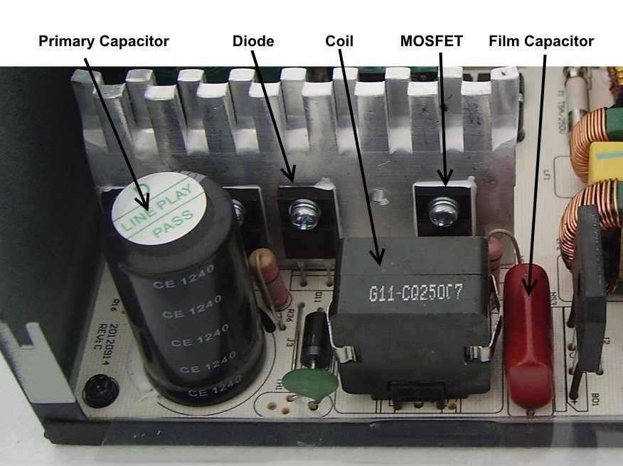
The other form of PFC (and nowadays the dominant form) is Active PFC. This is more complex than Passive PFC, with more components involved, but it does a far better job – typically bringing the power factor very close to the ideal 1.0. Like passive PFC, the components are located in between the bridge rectifier, and primary capacitor. It is essentially a boost converter (a type of SMPS) placed in this position. They consist of a film (preferentially polypropylene) capacitor, a transistor (almost invariably a MOSFET type), a high-speed diode, and a coil (which although larger than the input filtering coils, is much smaller than the coil used in passive PFC). The capacitor filters the high frequency pulses drawn by the converter. The transistor charges the coil when it is closed. When it is opened, the coil charges the capacitor in series with the AC allowing it to provide a very high voltage to the capacitor. The diode is used to rectify the pulsed current from the coil. The MOSFET and diode both require a heatsink in order to keep them at a safe operating temperature. In many power supplies, such as the Corsair VS450 pictured above, they are mounted to the same heatsink as the switching transistors (see below); other layouts may give them a separate heatsink.
Both types of PFC circuits do lose a bit of power – but on the larger scale, the wiring losses avoided by the current saving more than make up for it. The ‘spiky’ shape of the uncorrected current waveform can cause other insidious (and surprising!) problems – this is a very informative article on the topic.
The primary switching transistors (switchers)
Sometimes referred to a chopper transistors, these pulse the current into the transformer. They do so at a much higher frequency than the mains AC frequency – often from 50KHz up – over 1000 times higher than a 50Hz mains frequency. As stated earlier, this allows for a much smaller transformer. They also have the advantage of being able to adjust their duty cycle on the fly to maintain a fairly constant output voltage in spite of changes to the load and input voltage.
There are two types of transistors commonly used as switching transistors – Bipolar Junction Transistors (BJTs) and Metal Oxide Semiconductor Field Effect Transistors (MOSFETs). BJTs are used in the half-bridge topology – an obsolete design which is seen in old power supplies and current cheap and nasty ones. MOSFETs are used in forward converter and resonant designs, which is what all half-decent power supplies use these days. They offer much higher switching speeds and also lower internal resistances compared to BJTs, making designs that use them far more efficient.

The 5vsb transistor is actually part of a two-transistor circuit. They do a similar thing to the main switchers, only, they pulse the current in to the smaller 5vsb transformer. Some (especially newer) PSUs lack 5vsb transistors, and use circuits based on a switching IC such as a DM311. 2-transistor circuits can be quite destructive when they fail, which is sometimes caused by a critical capacitor failing. One classic example was the Bestec ATX-250-12E. The two-transistor 5vsb circuits in these PSUs would often fail catastrophically and the 5vsb output voltage would go way over 5v, as high as 18v in some cases – destroying the motherboards in the PCs they were installed in. These power supplies earned Bestec the nickname “Worstec”. Switching IC-based 5vsb circuits are better protected against fault events (such as a short circuit on the standby supply) and are less prone to over-volting, even if the capacitors go bad.
The stand-by supply, by the way, uses flyback topology. This requires the fewest parts, but at the cost of very high ripple currents – which place considerable stress on the output capacitors, even at the relatively low output current (some – even somewhat decent – units also under-rate the capacitor which accelerates its demise, especially if it’s also of poor quality).
The switchers are probably the most common failure point on cheap power supplies. When overloaded or overheated, they short internally, which can result in one of two things: Hopefully, the fuse will then blow and cut the power off, but if it doesn’t blow quickly enough, high voltage and high amounts of current will continue to be fed into the shorted transistor, which can cause it to explode. Many of the explosions seen in power supplies tested in the el-cheapo PSU roundups are because of the fuse failing to blow in time in spite of a shorted switcher.
The transformers
These change the voltage and isolate the secondary side from the mains. They are essentially a heap of wire coils (coated with very thin layers of heat-resistant plastics for minor insulation) wound around a plastic former, which in turn is fitted with a ferrite core. Layers of tape in between each set of windings provide additional insulation. In general, the bigger the core, the more power the transformer can handle.
![]()
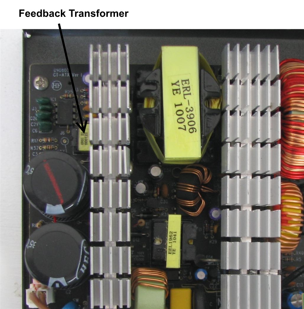
Like most PSUs, this Aywun A1-5000 has three transformers – the big main transformer, which generates the 12v, 5v and 3.3v voltages, the feedback transformer, which is part of the circuit that drives the switchers, and the 5vsb transformer, which generates the 5vsb voltage. On power supplies which use the two-switch forward converter topology, the feedback transformer is smaller, and is located on the primary side (as seen in the Cooler Power GX850 in the above right picture).
The secondary rectifiers
These do a similar thing to the bridge rectifier on the primary side, only allowing the current to flow one way, which avoids reverse-polarising the secondary capacitors. There are four common types of Rectifiers:
Standard rectifiers are used in linear power supplies, and as the primary bridge rectifiers on switching power supplies. However, they have very slow reverse recovery times (the time it takes for a diode to stop conducting when reverse-biased) – far too slow for acceptable performance on the secondary side of a switching power supply, so not even the cheapest of junk power supplies use them. They usually have peak reverse voltage ratings between 50V and 1kV (for >1kV, multiple diode junctions are wired in series) and a forward drop of about 1.0–1.2V at their full rated current.
Fast Recovery rectifiers and Ultra Fast Recovery rectifiers have much faster recovery times than standard diodes, but exhibit very high voltage drop characteristics – as much as 1.3V (even 1.7V for some 600V+ types) in some cases. If you were to pull 10A through such a diode, there would be 13W of power lost in the diode as heat – a considerable amount. Some old and/or cheap-and-nasty power supplies use such rectifiers on the 12V rail, but their high voltage drops make them unusable for the other rails.
Schottky rectifiers are more expensive, but they have even faster (practically instantaneous!) recovery. At low reverse voltage ratings (up to about 100–200V) they also present the lowest forward voltage drop (below 0.5V for the best types), though this rises (albeit non-linearly) as the reverse voltage ratings increase above 45V (and above ≈200V they start to lose ground to ordinary rectifiers, although the speed advantage stays); for this reason, it is recommended that the reverse voltage rating be just enough to allow for the highest peak voltage in normal operation. They are the only type of rectifier used on the 3.3V and 5V rails.
The rectifiers are generally 3-pinned components, with two internal diodes sharing a common cathode pin. These rectifiers can generate a lot of heat (more than the primary side components in many cases) and have to be attached to a heatsink. The 5vsb rail sometimes uses a smaller cylindrical diode rated at between 3 and 5A, which is not mounted on a heatsink, as it is not put under enough load to require one (although it can still get relatively hot). The −12V rail always uses these small diodes; they are usually Fast Recovery diodes, as the −12V rail is used very lightly if at all in modern PCs, and so its impact on the overall efficiency is negligible. The −12V rail is also sometimes equipped with a linear regulator (usually the venerable LM7912 or equivalent), which takes an input of −15~20V (filtered by a 25V rated electrolytic) and drops the ‘excess’ volts as heat. This is a little costlier to build, but provides a much cleaner and tighter-regulated −12V output (as long as the voltage input to the reg. is sufficient to avoid “drop-out”, which will cause it to stop regulating), although the regulator may get warm enough (if loaded to the label rating) to require a small heatsink. Yet another method occasionally used is to generate the −12V from a positive rail with a buck-boost converter (which provides an output of the opposite polarity from its input), which also provides tight regulation and is efficient, but requires its own control IC (plus switching MOSFET and rectifier diode).
Some (especially newer) power supplies use synchronous rectification, where MOSFETs are switched on and off at timed intervals. This is even more efficient than using Schottky rectifiers, and is usually required to achieve 80 Plus Gold certification.
Another technique used in many newer power supplies is to have only one rectification circuit for the 12V and use DC-DC conversion for the other two rails. As well as providing very high efficiency, this method also allows for rails to be regulated very tightly independently of each other.
In general, the rating of the rectifier is taken as the maximum amount of current that the rail is capable of delivering. However, there are a number of other factors that come into play, the biggest of which is the temperature. Most rectifiers are rated for what they can deliver at quite high temperatures. For instance, some common rectifiers such as the ON Semiconductors MBR20100CT and ST Micro STPS3045CW are rated for what they can deliver with their body at about 130°C − a temperature which is unlikely to be reached in a well cooled power supply (although the higher-powered fanless supplies may come close). If kept at lower temperatures, those same parts would theoretically be capable of delivering more (and, conversely, they will fail sooner if they are poorly cooled and allowed to heat up to their maximum junction temperature at a lower load). That said, in the interest of long-term reliability it’s advisable to stay well below the maximum temperature in normal operation.
The other major factor that comes into play is the duty cycle of the switching transistors. Exactly what effect this has, though, will vary depending the design of the secondary side. On a half-bridge (or resonant, although they more often use synchronous rectification) power supply, both diodes are used equally to rectify the output, and the maximum current of the rail is simply whatever the rectifier can deliver that its current temperature. For example, if an STPS3045CW rectifier was being run at its maximum temperature, the rail would be capable of 30A.
Forward topology, however, is different in that the diodes have two roles. One diode is used for rectification, while the other is used for discharging the coils (commonly known as freewheeling). This occurs when the switching transistors are in their ‘off’ state. So, when the rectifier diode is loaded when the switchers are in their ‘on’ state, and the freewheeling diode is loaded when they are in their ‘off’ state. In power supplies where the rectifier diode and freewheeling diode are on the same rectifier pack, this has little effect on the maximum current, since, being on the same chip, the temperature will stay roughly even between the two diodes.
However, if different rectifier packs are given different roles, then the duty cycle of the switching transistors will have an effect on the maximum output current. For instance, if one 30A rectifier pack was used for the main rectification and an identical part for freewheeling, then you would only get the maximum 60A rated current of the two at a 50% duty cycle. At a one third (33.33%) duty cycle (a more typical value), the maximum current would be closer to 45A, because the main diode will be conducting one third of the time (thus dissipating one third of the heat), while the freewheeling diode will be supplying the other two thirds. The design can be optimised for a one third duty cycle, either by using two rectifier packs for freewheeling, or by using a rectifier pack which is rated for double the output current of the main rectifier pack – but the theoretical maximum is not usable in practice, as the actual duty cycle of the power supply is always somewhat variable.
While rectifier packs may be run in parallel to reduce voltage drop and/or increase current capacity, their forward voltages must be matched carefully. Otherwise, the part with the lower forward voltage can ‘hog’ the current, which may (under the wrong circumstances) result in it being overloaded.
The secondary side rectifiers don’t go out with a fireworks display when they fail. The rectifier will short internally, causing the output voltage for whichever rail it is feeding to briefly spike, damaging attached hardware and the PSU’s SCP (Short Circuit Protection) will step in and shut the PSU down.

You can generally tell which rectifier serves which rail by its position in relation to the wires. In most PSUs, there are 3 main groups of output wires, one for the 3.3v rail, one for the 5v and one for the 12v. The rectifier for each rail is usually located behind the group of wires which it powers.
The output filtering
The output filtering is intended to smooth out the ripple in the current generated by the switching transistors. The 3 main rails as well as the 5vsb should have at least two capacitors and one filtering coil (often referred to as a PI coil), while the −12V rail is often OK with just one capacitor and a filter coil. Some very cheap and nasty units, however, omit the coil. As a result, the ripple can go above the maximum allowable limit in ATX specifications, which can cause stability problems and shorten the life of the PC it powers. Some even cheaper units also omit one of the capacitors, using just one capacitor per rail. This makes the ripple even worse. The Aywun A1-5000 (pictured below), however, does have all of the parts, so the ripple will be much better.

The capacitors on the secondary side are put under a lot more stress than the two on the primary side, so it is important for long term reliability of a PSU to use high quality ones. When the secondary filter capacitors fail, the ripple will go through the roof. One PSU with bad caps we connected to our oscilloscope was an Antec SP-350. The two capacitors on the 5vsb rail were Fuhjyyu branded (which is one of the worst brands available) and both were bulging. The PSU made a horrible high pitched squeal when plugged in and the ripple on the 5vsb rail was 5v. Yes, five volts of ripple. Not only is this above the maximum 50mv (0.05v) allowed in ATX specifications, but more than enough to damage a motherboard.
The Feedback and Protection
The feedback circuit is for monitoring the output voltages and adjusting the duty cycle of the switching transistors accordingly. The monitoring IC is responsible for collecting information on the output voltages and telling the PWM controller what to do with the switching transistors. It may also feature protections which shut the PSU down when necessary to avoid damaging it or the attached hardware. Over Current Protection (OCP) will shut the power supply down if too much current is drawn from one or more rails. Over Power Protection (OPP) steps in if the PSU is being overloaded, preventing the primary switching transistors from exploding. Over Voltage Protection (OVP) and Under Voltage Protection (UVP) step in when the voltages are too high or too low. Short Circuit Protection (SCP) kicks in when one of the rails is shorted by faulty hardware or when one of the secondary rectifiers shorts. Over Temperature Protection (OTP) shuts the PSU down when it gets too hot and prevents the PSU from starting again until it cools down.

The PWM controller is what turns the switching transistors on and off. It is responsible for adjusting their duty cycle, based on information it gets from the monitoring IC. In some cases, it can also be responsible for Over Power Protection. Power supplies based on the Half-Bridge topology generally have the all of the monitoring and control ICs located on the secondary side. On units based on Forward topologies, however, the PWM controller is generally located on the primary side. There are also some single ICs (such as the SG6105, which is used in some half bridge power supplies), which handle both secondary side monitoring and PWM control functions.
Discuss and Comment on this article: