Contents
- 1Introducing the Xilence XP400R6
- 1.1Packaging and accessories
- 2Connectors & cabling
- 2.1Casing & cooling
- 3Input filtering
- 4Primary side
- 4.1+5 V stand-by rail
- 5Secondary side
- 5.1Build quality
- 6Load testing
- 6.1Loading +5 V SB
- 6.2Voltage hold-up time
- 6.3Combined loading
- 6.4Combined loading ripple
- 6.5Crossloading, overloading
- 6.6Crossloading, overloading ripple
- 6.7Fan speed and temperatures
- 7Conclusion and evaluation
- 7.1Discussion
Primary side
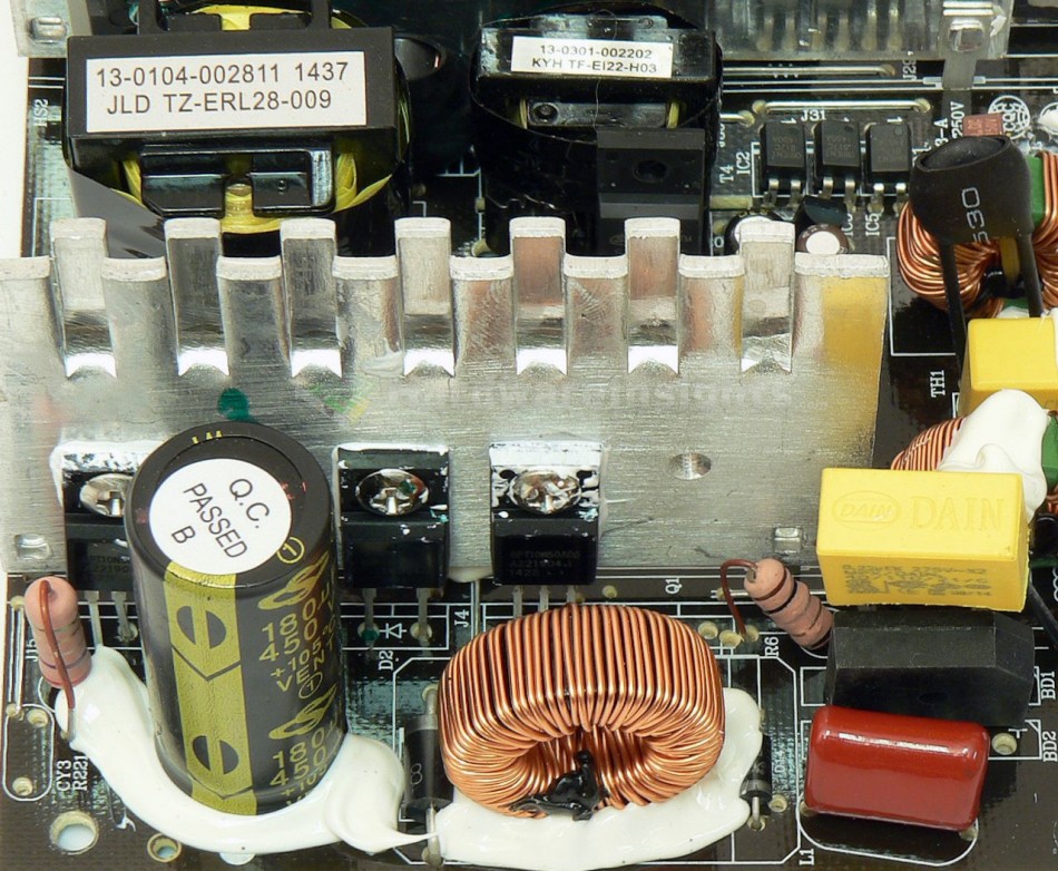
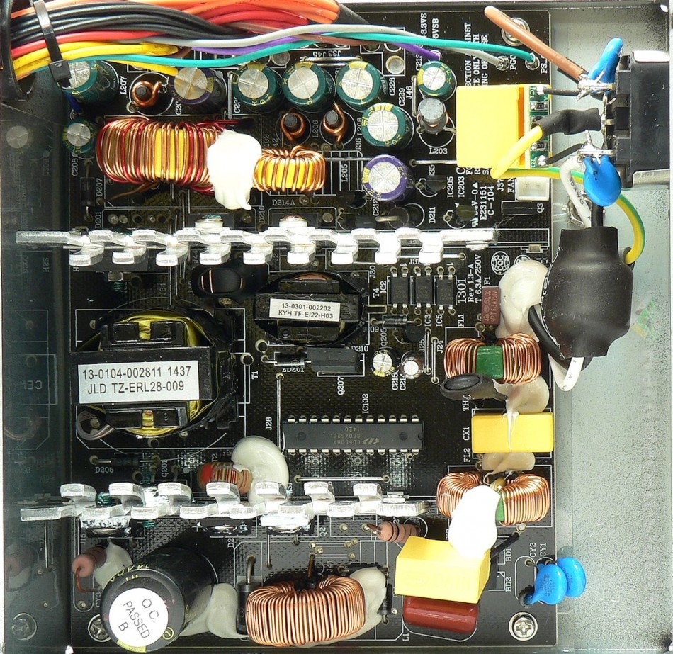
The primary side starts with a bridge rectifier, the ordinary KBL06. It has a pretty wide plastic body so it’s capable of operating without a heatsink and is capable of delivering 4 A continously or 200 A surge (8.3 ms) at 50 °C and 600 V. The voltage drop (which counts for losses) is 1.1 V per diode at 4 A and 25 °C. There is a single transistor in the PFC (boost type) circuit, the Shenzhen Great Power GPT10N50ADG (9.7 A continuous/29.1 A pulsed at 500 V and 25 °C, Rds(On) 0.7 Ω) in a TO-220FP package. The diode is a Champion Micro 5R06X which I could not find a datasheet for, and I expect it to be some sort of OEM part that’s sold together with driving ICs. If I had to guess, I would rate it at something in the area of 5 A @ 600 V.
The PFC coil is pretty small and uses thin wire. However, as this unit is only specified for a minimum input of 200 V and with a maximum of 250 W of continuous output power, I believe it should suffice. At that 400 W peak power, things might get slightly worse though, we shall see. The capacitor which is charged from the PFC circuit is also small, it is a Kuang Jin Enterprise branded 180 μF 450 V part (measures at 169 μF), but once again, this is only a 250 W unit…In the switching section are two more GPT10N50ADG transistors in a common two-transistor forward mode. All this silicon is mounted to the common primary heatsink which is just about thick and large enough for this kind of power.
A relatively new Champion Micro CU6808X microchip is used in this unit. It is intended for very cheap power supplies as it is a triple-function PFC + primary PWM + stand-by rail PWM in a single DIP-24 package. And finally, let’s address the main transformer, which is an ERL-28 that I think is capable enough for this power and efficiency bracket.
+5 V stand-by rail
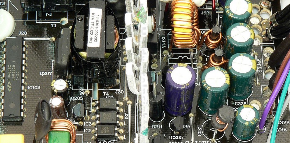
So yes, we have the CU6808X responsible for controlling the Silan Microelectronics SVF4N70F (4/16 A at 25 °C and 700 V, Rds(On) 2.7 Ω at 2 A) transistor in a TO-220F package, which acts as the power switcher. An EI-22 transformer is used. Some ChengX capacitors are used on the feedback.
There’s a single DO-package diode for single-way rectification. The blue cap in front of the Pi coil is Kingkong Kingcon 1000/10 of “LOW E.S.R” series and the small green one after the coil is another ChengX, 470/10 of the GR series. Eh.


