Contents
- 1Introducing the Xilence XP400R6
- 1.1Packaging and accessories
- 2Connectors & cabling
- 2.1Casing & cooling
- 3Input filtering
- 4Primary side
- 4.1+5 V stand-by rail
- 5Secondary side
- 5.1Build quality
- 6Load testing
- 6.1Loading +5 V SB
- 6.2Voltage hold-up time
- 6.3Combined loading
- 6.4Combined loading ripple
- 6.5Crossloading, overloading
- 6.6Crossloading, overloading ripple
- 6.7Fan speed and temperatures
- 7Conclusion and evaluation
- 7.1Discussion
Secondary side
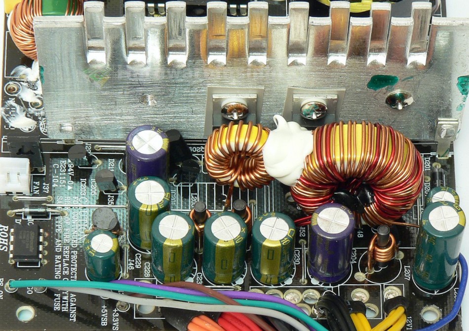
Oh yeah, group design with magamp’ed +3.3 V, we could have not expected anything else. What does surprise me, and in a positive way, is that this silicon is actually not drastically underrated. Quite the opposite. I may even give a point or two for this (only if firstly though it manages to even pass its spec).…It has a big TO-247 rectifier for the +12 V rail, the MOSPEC S30D60C (30/300 A at 60 V and 125 °C, drop of 0.7 V at 15 A and 25 °C). Then, a S20C45C (20/200 A at 125 °C and 45 V, drop of 0.55 V at 25 °C and 10 A) in TO-220 for both the +3.3 and +5 V rails. The inductors do not seem too small and the thing actually even has full Pi filter for each rail (well, not counting the −12 V) with two ChengX 1000/10 caps per +3.3 and +5 V and a 2200/16 coupled with a 1000/16 for the +12 V.
As for the secondary monitor, we have the Sitronix ST9S313-DAG acting as the OVP, UVP and SCP supervisor, while also providing the Power Good signal and accepting the PWR On signal from the motherboard which turns the unit on. As for the fan control, there is a tiny SMD thermistor soldered to one of the outputs (common) of the main transformer, so it will take the temperature reading directly from it. I guess that because the secondary heatsink is rather large, they found it more appropriate to get the heat reading from the transformer instead. A PNP transistor (2SB772, −3 A/−60 V) in a SOT-32 package drives the fan.
Build quality
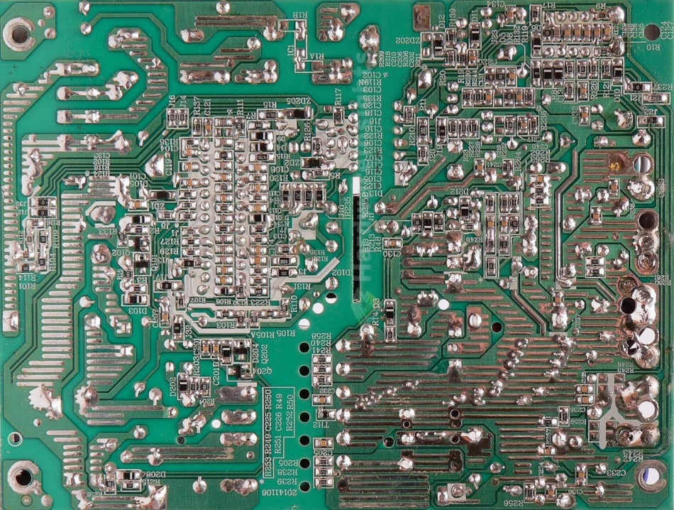
As usual, I’ll focus on the overall build quality and other things like electrical safety here, as the quality of the components that were used was already discussed before. The separation between the primary and secondary sides is adequate, and we also have some extra holes that were drilled under the main transformer for extra cooling. Overall component insulation is within acceptable parameters for a mainstream unit, even though for my tastes some of the components could have been placed further apart. On the other hand they are mostly covered with a protective coating.
Conductive paths are reinforced by layers of solder, which is nice, but considering that this is only a 250W unit, I don’t think it is necessary. The soldering of the XP400R6 itself is actually quite OK, even though the SMD components could have been soldered a little bit better. There are a couple of joints I would personally have paid more attention to, but overall, it is otherwise nice and clean. Most of the leads have been adequately trimmed, and there’s insulation foil beneath the PCB. Either I’m going blind, or there really only was a single stray solder ball on this unit… Well, that means I’m only going to deduct two points in this area.


