Contents
- 1Introducing the Zalman ZM600-GVM
- 1.1Packaging and accessories
- 2Connectors & cabling
- 2.1Casing & cooling
- 3Input filtering
- 4Primary side
- 4.1+5 V stand-by rail
- 5Secondary side
- 5.1Build quality
- 6Load testing
- 6.1Loading +5 V SB
- 6.2Voltage hold-up time
- 6.3Combined loading
- 6.4Combined loading ripple
- 6.5Crossloading, overloading
- 6.6Crossloading, overloading ripple
- 6.7Fan speed and temperatures
- 7Conclusion and evaluation
- 7.1Thanks
- 7.2Discussion
Secondary side
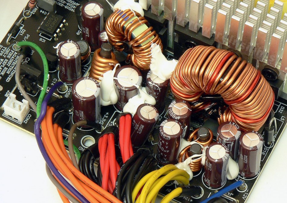
The secondary side is basically the same as within the 500W version. The +12 V rail uses four PFC Device Corporation PFR30L60CT Schottky rectifiers this time (30/250 A at 25 °C and 60 V, drop of 0.6 V at 15 A) in a TO-220 package, connected in parallel. This should prove interesting, especially since the unit is supposed to provide 45 A on this rail…the remaining rails look better equipped, as they use the TO-247 MOSPEC S30D45C (30/300 A at 125 °C and 45 V, drop of 0.55 V at 25 °C). As for filtration, we have two Chemi-Con KY 1000/16 caps before and after two Pi coil filters for the +12 V, 1+1 KY 1000/10 for the +5 V and a pair of 2200/6.3 for the +3.3 V. The −12 V rail uses a single 1000/16. The inductors seem adequate enough.

The thermistor for the fan speed regulation is glued with silicon to the heatsink, which also has more fins. There is still the 8-pin Grenergy GR8313 secondary monitor, which obviously monitors only three things: undervoltage, overvoltage and a potential state of a short-circuit. As well, it also provides the Power Good signal and monitors incoming PWR On signal from motherboard. Still no over current protection and very bad UVP/OVP characteristics. Also the modular board is the same with 18AWG wires, the spots for some small filtering capacitors are still unpopulated. Other than that, it only houses some ordinary PCIe and EPS connectors.
Build quality
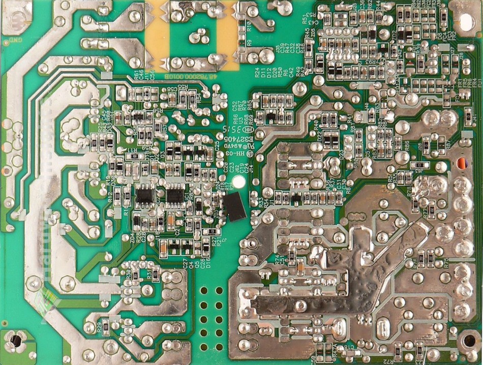
As usual, I’ll focus on the overall build quality and other things like electrical safety here, as the quality of the components that were used was already discussed before. The separation between the primary and secondary sides is adequate, and we also have some extra holes that were drilled under the main transformer for extra cooling. Both the varistor and the thermistor are sleeved with heatshrink, and the same goes for some leads that are in close proximity to other components. There is even a tooth-shaped pattern on the PCB under the common-mode chokes, which is most likely for arc suppression during high-voltage spikes. The glue used to hold components before wave-soldering took place is some kind of silicone, and although I’ve seen it applied more liberally before, I can’t exactly say that they were saving it for a rainy day here.
Conductive paths are reinforced by thick layers of solder, and the secondary common ground is even reinforced by a thick metal shunt (probably copper). The soldering itself is not that bad for an inexpensive unit though this time there are some remains of soldering flux. Also there are more small joints some of which may tend to crack over time. I found three rework bodges, on the other hand only a single solder ball. The overall build quality of this unit seems more or less OK, and I shall deduct only three points here for the Zalman ZM600-GVM…


