Contents
- 1Introducing the Zalman ZM600-LX
- 1.1Packaging and accessories
- 2Connectors & cabling
- 2.1Casing & cooling
- 3Input filtering
- 4Primary side
- 4.1+5 V stand-by rail
- 5Secondary side
- 5.1Build quality
- 6Load testing
- 6.1Loading +5 V SB
- 6.2Hold-up time
- 6.3Combined loading
- 6.4Combined loading ripple
- 6.5Crossloading, overloading
- 6.6Crossloading, overloading ripple
- 6.7Fan speed, temperatures and noise
- 7Conclusion and evaluation
- 7.1Bonus
- 7.2Thanks
- 7.3Discussion
Primary side
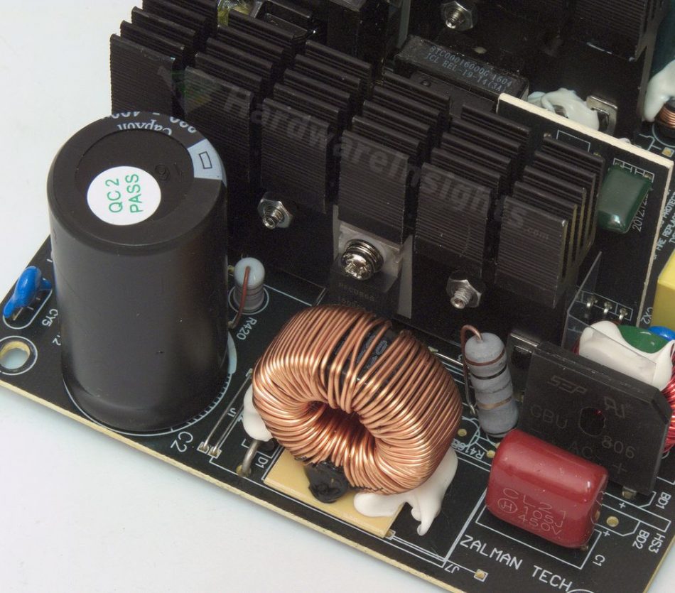
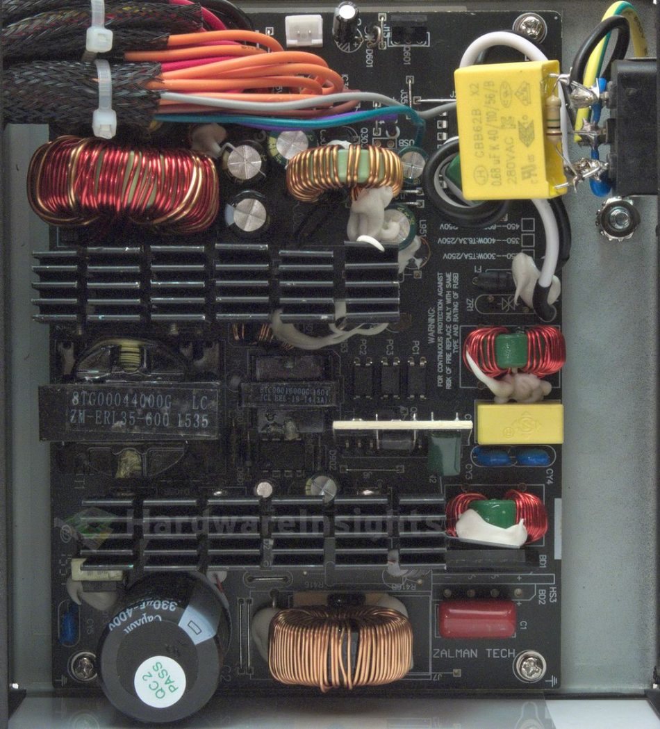
The primary side of the ZM600-LX starts with an input bridge rectifier, the GBU806. This one handles a current of 8 A continuous at 100 °C or 200 A peak surge (for 8.3 ms) at 600 V. That is only with heatsink though, so here it’s actual rating should be less than 4 A. The voltage drop is 1.0 V per diode at 4 A. The PFC consists of a medium sized PFC choke with rather thin wire for the winding. It does not necessarily need to be that large though for 230V nominal input, but still, there will be losses here. There is just a single transistor used for the boost stage, the SL SEMI SLF18N50C (18/72 A at 500 V and 25 °C, RDS(On) 0.32 Ω at 9 A) in a TO-220F package. The diode in the circuit is the Champion Micro CMPFCD86G (8/200 A at 600 V and 140 °C, drop of 1,5 V at 8 A and 25 °C) in a TO-220AC package.
The capacitor charged by the PFC circuit is the CapXon LP 330 μF/400 V, which measures at 322 μF. This series is rated for just 2000 hours at 85 °C at its maximum rated ripple current. If you are to believe C(r)apXons datasheet of course. The main switchers are also from SL SEMI, but weaker parts, SLF16N50C (16/64 A at 500 V and 25 °C, RDS(On) 0.38 Ω at 8 A ) also in a TO-220F package. Of course, all this in the usual two-transistor forward topology, as Zalman likes to remind us everywhere. All the primary silicon uses a common primary heatsink with large fins. It’s going to need it to dissipate about 40–50 watts of heat…
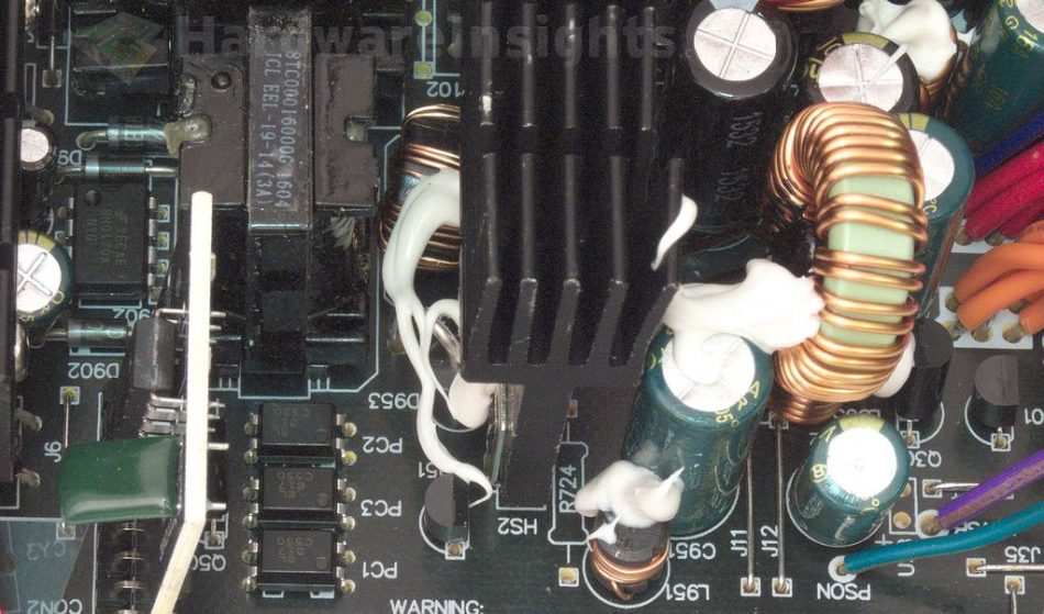
As could be expected, a Champion Micro controller has been chosen to drive the unit. It is the well-known CM6800TX PFC/PWM combo controller located on a daughterboard next to the stand-by rail. A ChengX capacitor (GR 220/35) has been selected to filter its power supply. The main transformer is an ERL-35 type which should be enough for 600 W.
+5 V stand-by rail
The stand-by power supply uses PWM driver with an integrated MOSFET from Fairchild, the FSBH0170A. This driver can supply up to 15 W continuously in open-frame circuits with a 230V input. Another ChengX capacitor is used to filter its own power supply, CD110 47/25. The transformer is ‘EEL-19’.
A Schottky diode in a DO package rectifies the transformer output. There are more garbage capacitors that then filter the output, namely ChengX GR 2200/16 and 1000/10. Let’s move on…


