Contents
- 1Introducing the Zalman ZM750-EBT
- 1.1Packaging and accessories
- 2Connectors & cabling
- 2.1Casing & cooling
- 3Input filtering
- 4Primary side
- 4.1+5 V stand-by rail
- 5Secondary side
- 5.1Build quality
- 6Load testing
- 6.1Loading +5 V SB
- 6.2Voltage hold-up time
- 6.3Combined loading
- 6.4Combined loading ripple
- 6.5Crossloading, overloading
- 6.6Crossloading, overloading ripple
- 6.7Fan speed, temperatures and noise
- 7Conclusion and evaluation
- 7.1Thanks
- 7.2Discussion
- 8Important addendum
Secondary side
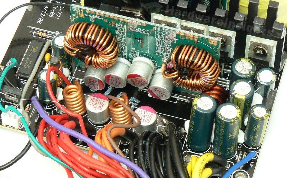
Four transistors are responsible for the synchronous rectification of the +12V rail, and they are the International Rectifier IRFB7437 (250/1000 A at 40 V and 25 °C, RDS(On) 2 mΩ at 100 A) in a TO-220 package. The actual limit of the bonding material is only 195 A continuous, only the junction can actually withstand 250 A. I think this part sets a personal record for me with regards to how much power a low-voltage transistor can move. The pi filter consists of two pairs of SC 2200/16 capacitors and a coil that has some pretty thick wire. Two more Teapo CG polymer capacitors provide additional filtering directly on the single DC-DC board. For the output, two CF 1500/6.3 polymers are used for both the output rails. The −12 V rail still uses a −12V regulator, the KEC Semiconductor KIA 7912P with 5 % regulation. There’s an SC 470/25 on the input and a 1000/16 on the output.
Both the converters use four Infineon IPD060N03L G (50/350 A at 30 V, RDS(On) 9 mΩ at 30 A and VGS of 4.5 V or 6 mΩ at 10 V) transistors in a TO-252-3 package (each). As always, the dual-channel Anpec APW7159 buck controller is used. There is also a stand-alone secondary side monitor (and PG generator/PWR On receiver), which is the usual Silicon Touch Technology PS223. Here it of course only monitors the +12V rail OCP, then UVP, OVP and OTP. The thermistor sensor is screwed to the secondary heatsink. The HT772 PNP transistor (−7 A/−30 V) from Hi-Sincerity Microelectronics corporation in a TO-126 package acts as the linear regulator of the fan. The modular board is soldered by a few thick (14AWG) wires.
Build quality
As usual, I’ll focus on the overall build quality and other things like electrical safety here, as the quality of the components that were used was already discussed before. The separation between the primary and secondary sides is good, and we also have some extra holes that were drilled under the main transformer for extra cooling. The varistor is not sleeved with heatshrink and there is no thermistor present. As Sirtec tried to squeeze oversized components into the limited space, some components are too close to others, but they did not add any additional insulation. This is especially the case for the input capacitor which almost touches the heatsink and the PFC coil. I do not like this at all. The primary and secondary sides separation is good though.
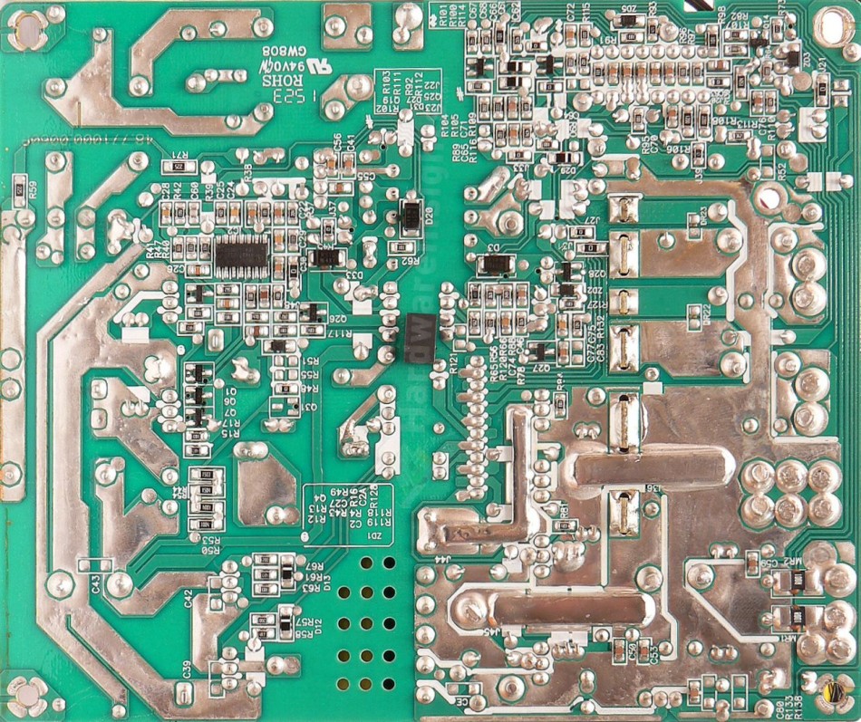
Rather large quantities of silicone have been used to fix the components in place. The soldering quality is good, everything is quite clean and the leads are well trimmed. Conductive paths are reinforced by a layer of solder as well as some copper plates. The same applies to the modular board. It is worth noting that this time Sirtec payed a lot of attention to the ground reference – there is a special wire connecting the secondary return with earth grounding from one screw, and than some wire jumpers from another screw. I only noticed a single spot which was manually resoldered by hand and only found a single tiny loose solder ball. So for the overall build quality, I’ll deduct only three points.


