Contents
- 1Introducing the Antec High Current Gamer M 750 W (HCG-750M)
- 1.1Packaging and accessories
- 2Connectors & cabling
- 2.1Casing & cooling
- 3Input filtering
- 4Primary side
- 4.1+5 V stand-by rail
- 5Secondary side
- 5.1Build quality
- 6Load testing
- 6.1Loading +5 V SB
- 6.2Hold-up time
- 6.3Combined loading
- 6.4Combined loading ripple
- 6.5Crossloading, overloading
- 6.6Crossloading, overloading ripple
- 6.7Fan speed, temperatures and noise
- 7Conclusion and evaluation
- 7.1Thanks
- 7.2Discussion
Primary side
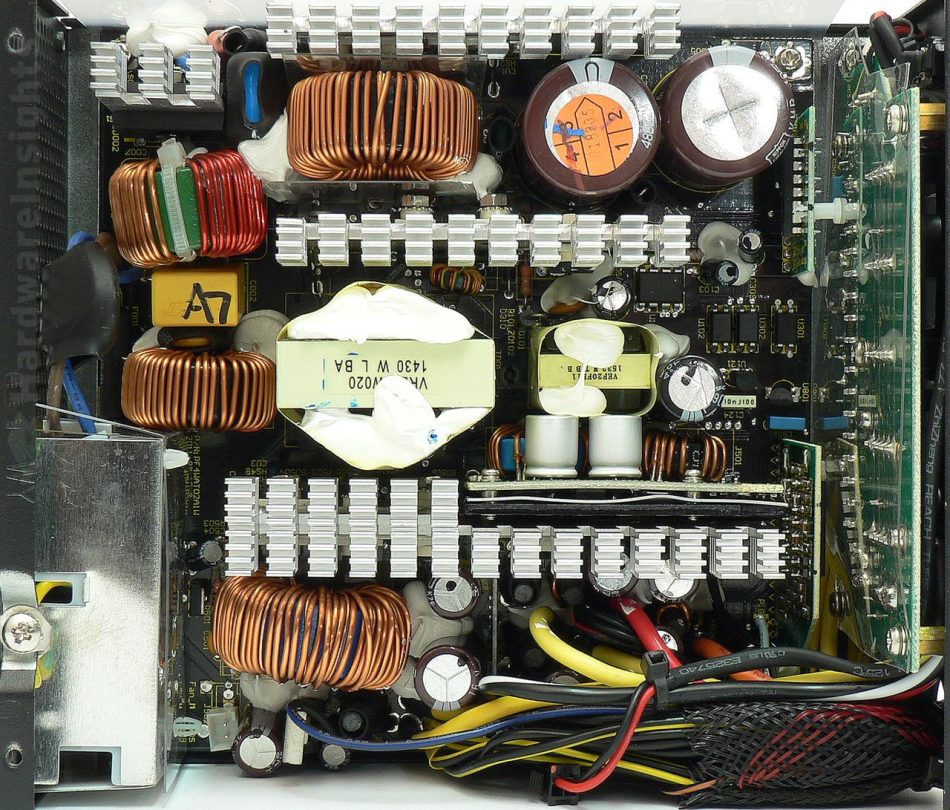
The primary side starts with input bridge rectifiers (two of them in parallel), the GBU8J. They can handle 8 A continuously at 600 V and 100 °C, or 200 peak (for 8.3 ms). The voltage drop is 1 V per diode at 8 A. Both are attached to a separate aluminium heatsink. Then there is quite massive PFC choke, but with not that many turns of wire. The power silicon operating the PFC consists of three transistors which have separate heatsink. They are the Fairchild FDP18N50 (18/72 A at 500 V and 25 °C, RDS(On) 0.265 Ω at 9 A and 25 °C) in TO-220 package. The diode then is the ST Micro STTH8S06D (8/60 A at 600 V and 25 °C, drop of 1.9 V at 125 °C or 3.4 V at 25 °C) in TO-220AC package. It is mounted on second heatsink together with switching transistors. Note that all the heatsinks in the unit are the same, clearly cut from long extrusions of the same style. Both the primary ones even have the same length.
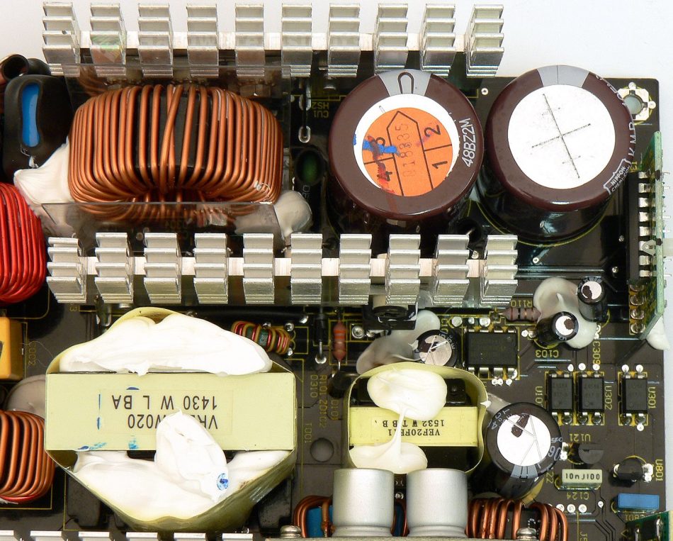
As for the bulk capacitors charged from the PFC, there are two of them, both Nippon Chemi-Con KMR, one is 330 μF/400 V and one 220 μF/400 V. I have measured capacity of 481 μF. This series has a minimum lifetime of 2000 hours at maximum temperature (105 °C) and ripple. The switching transistors they feed are Infineon SPP20N60C3 (20.7/62.1 A at 650 V and 25 °C, RDS(On) 0.19 Ω at 25°C, 0.43 Ω at 150 °C) in TO-220 package, in the usual two-transistor forward configuration. The power is then transformed to secondary side through a transformer with 39mm core. There is huge amount of silicone in the transformer, I wonder whether it has something to do with reported whining/whistling problems of some Seasonic units.
As for the driving circuitry, there is the Champion Micro CM6802TBHX microchip, located on a daughterboard next to the input capacitors. This is the newest generation of PFC/PWM primary combo chips, one of its interesting functions is the green mode. In green mode, the IC can provide PFC turned on even with no-load condition (with older chips, PFC was usually turned off), but still keeping low power consumption (less than 0.75 W). Its clock frequency can also be driven externally up to 250 kHz. Its power input is filtered by Rubycon YXG 4.7/50 capacitor.
+5 V stand-by rail
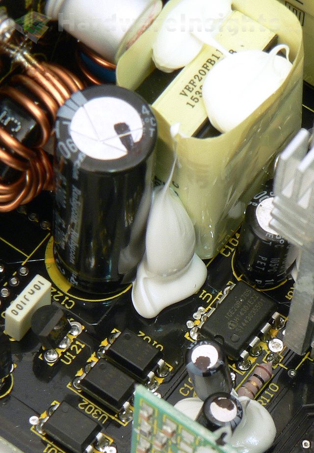
The stand-by rail is very similar to other Seasonic units. It uses the Infineon ICE2QR4765 quasi-resonant PWM controller with integrated transistor (with RDS(On) of 4.7 Ω). Its power is filtered by Rubycon YXG 10/50. The transformer in use has 20mm core.
As usual, a Diodes SBR10U45 (10/125 A at 45 V, drop of 0.57 V at 10 A and 25 °C) rectifier is used. It comes in TO-252 SMD package so it is on the bottom soldering side. There is a big capacitor in the output Pi filter, Rubycon ZLH 3900/16, combined with Chemi-Con KY 1000/16 located by the output cable.


