HIGH QUALITY, HARD TO GET AND CUSTOM ELECTROLYTIC CAPACITORS FOR POWER SUPPLIES, DISPLAYS, TVs, MOTHERBOARDS AND MORE!

Proprietary motherboard (HP, Dell…) connector pinouts

Discuss and get help with Motherboards and PCI cards in this part of the forum.

Proprietary motherboard (HP, Dell…) connector pinouts

Postby Behemot » November 16th, 2017, 12:56 pm

I recently required many different motherboards for some order and naturaly run into some proprietary boards from tier 1 PC manufacturers which could be acquired quite cheap, unlike the retail variants. Since I am not the only one who ever run into the problems with the boards having proprietary connectors or component presence detection (especially Dell is ill with this), lets check some of those.

The first one is the Dell Inspiron 570 board, 04GJJT. It has AM3 socket, chipset AMD 785G/SB710 and quite the ordinary uATX layout with normal conenctors, with the exception of front panel one. It requires to run something on the fan header near the NB and to ground the presence pin of the green F_USB1 header. That means either really putting some 9pin USB header on it, or just jumpering pins 8 and 10.
04GJJT.jpg
04GJJT.jpg (291.26 KiB) Viewed 69902 times

Here is also the front panel pinout (as is on the board):
header.PNG
header.PNG (473 Bytes) Viewed 69902 times

The pins 5 and 9 are jumpered with a wire (I myself soldered it beneath, though it does not seem to be actually sensing anything here as it uses F_USB1 sense pin to detect the front panel). The #6 appears to be PWR On + (+3.3 V), the pin #5 is GND. The others are #1-PWR LED +, #2-PWR LED -; #3-HDD LED +, #4-HDD LED -. Pins #7 and #8 are not connected as these PCs usually don't have the reset button.
User avatar
Behemot
Administrator
 
Posts: 455
Joined: November 28th, 2014, 8:57 am
Location: CZ

Re: Proprietary motherboard (HP, Dell…) connector pinouts

Postby Behemot » November 19th, 2017, 9:27 am

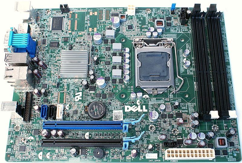
The second board is even more complicated. It is an Optiplex 790 board, D28YY, with Socket 1155 and Q65 chipset. It has an unusual long shape but its mounting holes fit the first two rows of a standard Full ATX board mounting. If you case is deep enough it should fit just fine.
D28YY.jpg
D28YY.jpg (170.2 KiB) Viewed 69887 times

This board has several specialty connectors. First of all, it uses the Dells 5pin fan headers (which are actually 4pin PWM with blank fifth pin). You can get cheap adapters from fleebay, or make your own with this pinout:
idc5m.gif
idc5m.gif (185 Bytes) Viewed 69887 times

thumb_idc5m.jpg
thumb_idc5m.jpg (5.84 KiB) Viewed 69887 times

Between this and the standard Mini-DMI with PWM, just the first and third pins are swapped:
#1: sense/tach
#2: +12 V
#3: GND
#4: PWM
#5: unused

The next one is the PWR button/LED header, located near the CPu fan header and DIMM banks. Dell uses a power button which is backlit with orange LED when turned off, and a blue (or green) one when turned on. There is a 5pin header with smaller than standard pitch so you could not easily fit standard-pitch (i think 2.5mm). I have just used a piece of standard IDC and soldered it into the board with short wires instead of the whole original connector. For standard case, use On LED pins so it lights only when the PC is turned ON. You have to short the PWR On + to #4 to get rid of the PWR button failure message.
header.PNG
header.PNG (458 Bytes) Viewed 69887 times

#1: PWR On -
#2: PWR On + (also shorted to #4)
#3: On LED - (Off LED +)
#4: shorted to #2
#5: unused
#6: On LED + (Off LED -)

The last and worst one is the combined front panel header. Dell combined four USB, couple LEDs and also HD audio in/out jacks into single 34pin connector with the same smaller pitch. If you need these ports, it is most likely cheaper to just buy the whole connector set from fleebay (or possibly at least cut the connector and attach it to your standard case ports). This is quite common part for other Dell boards too, one of the variants is this one:
Hxa2Lz2.png
Hxa2Lz2.png (15.49 KiB) Viewed 69887 times

I acquired two of the original ports from fleebay under PN of 87G1H just for the worst case, in this case the +5V cables are red and blue, but that does not change much. Also all the LED/audio cables were only the usual grey ribbons. Anyway, if you only want to get rid of the annoying message about front panel failure, Dell uses the two common pins in the audio section as feedback sense. as the are actually grounded from the USB ports and only than lead back to the board.
fix.PNG
fix.PNG (16.61 KiB) Viewed 69887 times

You can either use some of the ground pins, or just solder both pins together using short (about 1cm) piece of wire on the solder side, also connected to for examle the nearby audio ports shielding which is grounded. Very easy and you make the board think the bloody think the panel is connected! Remember you also have to have the system fan (by the Main ATX connector) plugged in, the PWR button, the CPU fan of course and a hard drive too. Lacking any of these things triggers some of the bloody messages and you have to hit F1 after each reboot.
User avatar
Behemot
Administrator
 
Posts: 455
Joined: November 28th, 2014, 8:57 am
Location: CZ

Re: Proprietary motherboard (HP, Dell…) connector pinouts

Postby Behemot » December 18th, 2017, 11:00 am

This time an HP board which also catched these stupid manners. It is MSI MS-7860 ver. 1.20 from ProDesk 400 G1 tower PCs but these tips should work on many more boards. It requires detection of USB 2.0, USB 3.0 and HD audio pin header connections. Of course it is easiest to just plug some in, if you have some newer case, you should have all of them already. If you do not need or want, you have to make the board fool they are connected.

With USB 2.0 it is pretty straightforward, as usually, ground the presence pin (the single 9th one) with a jumper just to the next GND. USB 3.0 works the same way, you just need to identify the right pins, which is the corner one (pin 10, presence/ID) and some of the GND pins, I used number #6, connecting them with small jumper wire soldered to the soldering side.
USB_3.0.PNG
USB_3.0.PNG (12.48 KiB) Viewed 69809 times

Next one is the HD audio header where once again, jumpering the presence pin to ground (#2 and #4) with a jumper is just enough.
HD_audio.png
HD_audio.png (63.27 KiB) Viewed 69809 times

Than you also need to have the sys fan connected, slight problem is that there is the original 4pin NSL connector, and the usual 4pin PWN fan header has slightly narrower plastic key. All you need to do is to cut the side of the plastic key just enough so a 3pin or 4pin fan could be plugged in, the pinout is standard (ground, voltage, tach and PWM).

That does it for fooling the board everything is connected. The last one is to connect the power button and LEDs P5, PB/LED). As usually, no reset here. It also seems that the #8 and #10 are to be connected using a wire jumper although in my case the board did not complain regarding power button, but if your does, this might solve it. Other than that, we have:
- Power button: #7 PWR_On+ and #8 GND
- Power LED: #2 PWR_LED+ and #4 PWR_LED-
- HDD LED: #1 HDD_LED+ and #3 HDD_LED-
P5_PB_LED.PNG
P5_PB_LED.PNG (481 Bytes) Viewed 69809 times
User avatar
Behemot
Administrator
 
Posts: 455
Joined: November 28th, 2014, 8:57 am
Location: CZ


Return to Motherboards & Add-In Cards

Who is online

Users browsing this forum: No registered users and 2 guests