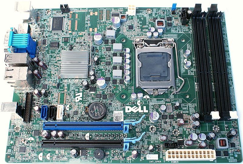
The second board is even more complicated. It is an
Optiplex 790 board,
D28YY, with Socket 1155 and Q65 chipset. It has an unusual long shape but its mounting holes fit the first two rows of a standard Full ATX board mounting. If you case is deep enough it should fit just fine.

- D28YY.jpg (170.2 KiB) Viewed 105043 times
This board has several specialty connectors. First of all, it uses the Dells 5pin fan headers (which are actually 4pin PWM with blank fifth pin). You can get cheap adapters from fleebay, or make your own with this
pinout:

- idc5m.gif (185 Bytes) Viewed 105043 times

- thumb_idc5m.jpg (5.84 KiB) Viewed 105043 times
Between this and the standard Mini-DMI with PWM, just the first and third pins are swapped:
#1: sense/tach
#2: +12 V
#3: GND
#4: PWM
#5: unused
The next one is the PWR button/LED header, located near the CPu fan header and DIMM banks. Dell uses a power button which is backlit with orange LED when turned off, and a blue (or green) one when turned on. There is a 5pin header with smaller than standard pitch so you could not easily fit standard-pitch (i think 2.5mm). I have just used a piece of standard IDC and soldered it into the board with short wires instead of the whole original connector. For standard case, use On LED pins so it lights only when the PC is turned ON. You have to short the PWR On + to #4 to get rid of the PWR button failure message.

- header.PNG (458 Bytes) Viewed 105043 times
#1: PWR On -
#2: PWR On + (also shorted to #4)
#3: On LED - (Off LED +)
#4: shorted to #2
#5: unused
#6: On LED + (Off LED -)
The last and worst one is the combined front panel header. Dell combined four USB, couple LEDs and also HD audio in/out jacks into single 34pin connector with the same smaller pitch. If you need these ports, it is most likely cheaper to just buy the whole connector set from fleebay (or possibly at least cut the connector and attach it to your standard case ports). This is quite common part for other Dell boards too, one of the variants is
this one:

- Hxa2Lz2.png (15.49 KiB) Viewed 105043 times
I acquired two of the original ports from fleebay under PN of 87G1H just for the worst case, in this case the +5V cables are red and blue, but that does not change much. Also all the LED/audio cables were only the usual grey ribbons. Anyway, if you only want to get rid of the annoying message about front panel failure, Dell uses the two common pins in the audio section as feedback sense. as the are actually grounded from the USB ports and only than lead back to the board.

- fix.PNG (16.61 KiB) Viewed 105043 times
You can either use some of the ground pins, or just solder both pins together using short (about 1cm) piece of wire on the solder side, also connected to for examle the nearby audio ports shielding which is grounded. Very easy and you make the board think the bloody think the panel is connected! Remember you also have to have the system fan (by the Main ATX connector) plugged in, the PWR button, the CPU fan of course and a hard drive too. Lacking any of these things triggers some of the bloody messages and you have to hit F1 after each reboot.
