UPDATE: If you don't have over-wide plug-packs and aren't bothered by the length of a normal board, the Kaifeng KF‑MSD‑4A (and KF‑MSD‑6A) are at least as well-made and cost about half as much as these.However I'm not yet aware of a better-made cube, and these
are reasonably priced for their more-complex construction, so you can still consider them.
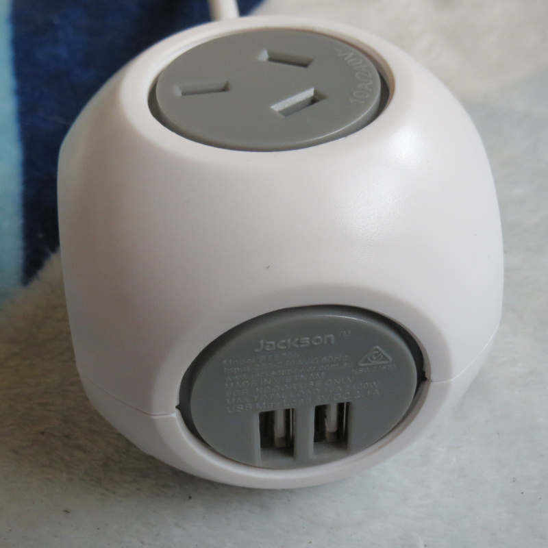
I was at Bunnings for some unrelated (and mostly non-electrical) items, when I came across this:
- Overview.JPG (154.63 KiB) Viewed 215734 times
If you remember the original Allocacoc PowerCubes, I didn't have the best
outcome with their build quality. Could this actually be better-made?
This version (also available with
red or
blue socket faces) provides 2.1A USB charging and 4 mains sockets (3 usable when mounted), but as is the case with the PowerCube, you can also get a
non-USB version with another mains socket (and black socket faces) for AU$10 less.
They're listed at AU$32 (USB)/AU$22 (non-USB), which is similar to (or even a bit cheaper than) the Allocacoc versions.
Jackson Industries are one of the prominent name-brands for power-related end-user products in Australia (and NZ), competing with Crest (which I mentioned before as providing
the lesser-evil among conventional power-boards). My prior impression of this company was so-so, but perhaps this will improve on that…
It's a sphere truncated to flat faces at the sockets, rather than a cube proper; it's also a bit bigger than PowerCubes, at 71mm flat-to-flat (85mm spherical diameter).
Here, the circuit breaker reset button is accessed via a hole at the top of one socket; the mounting base is screw-on instead of twist-lock. This base supports adhesive (though not as easily removable) or screw mounting, but unlike the PowerCubes, the screws are actually included. The hole pitch here is 26mm.
The finish is a more-pleasant matte texture (versus the gloss on the Cubes), but whether the plastic will last as well before yellowing is another matter (it doesn't say what type, and feels most like ordinary ABS to me). The cord is shorter at 0.9m, but at least that's stated accurately (within 2cm); it feels flexible enough.
The casing screws here, while not hidden behind a nameplate, require a notched-blade screwdriver to engage; in my case I took an old cheap screwdriver and cut the notch myself. Depending on the width of the screwdriver, you might also need to grind its sides down to fit. The two above the socket (as referred to their normal orientation at wall outlets) are slightly longer (12mm) than the two below it (10mm), although any justification for this isn't apparent in the casing design.
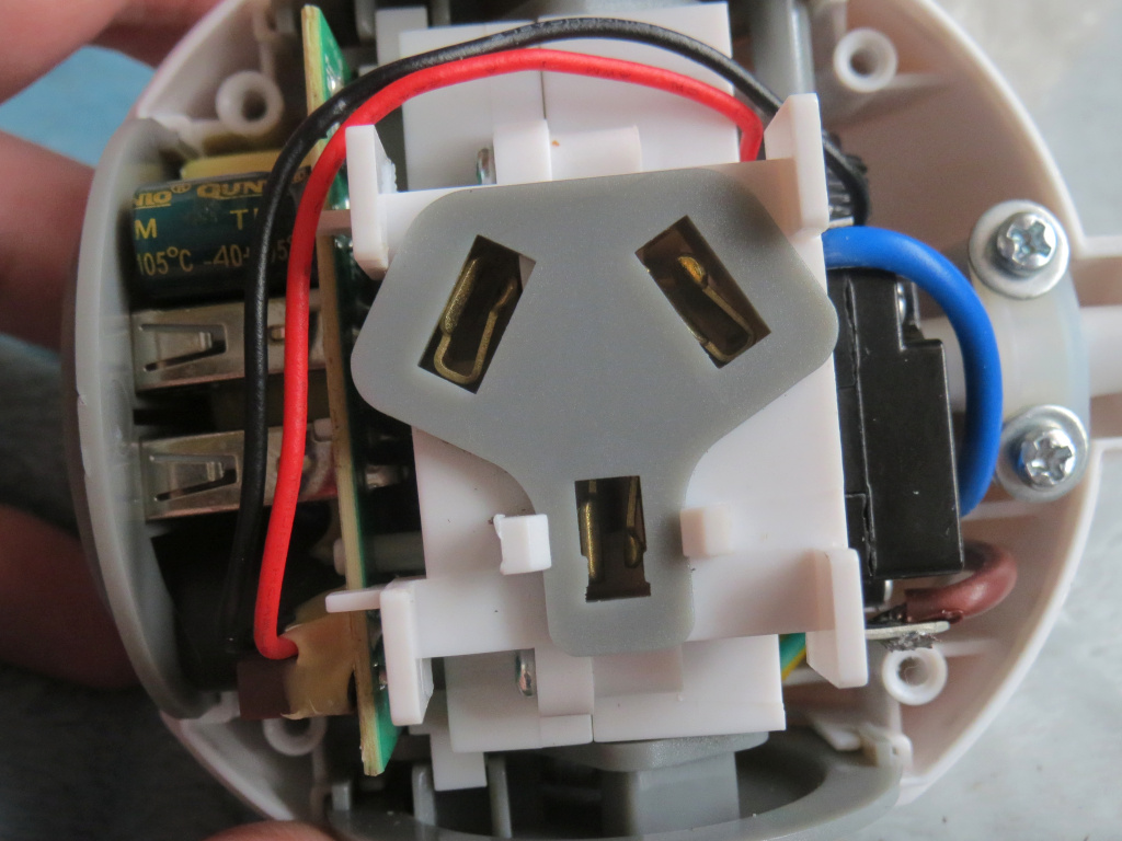
Outlet block
- Inside.JPG (251.03 KiB) Viewed 215734 times
- Contacts.JPG (222.69 KiB) Viewed 215734 times
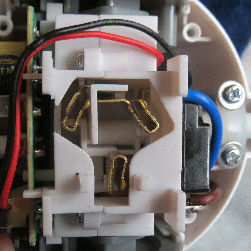
Peering through the packaging, I could see that the contacts are a different (and hopefully more robust) design from the majority of modern Australia/NZ (and many USA/Canada) power-boards: A sideways-wiper arrangement, like that used (in a smaller form) in many IEC 60320 C13/C15(A)/C17 and C19/C21 connectors.
(The prevalent form involves busbar sections stamped to both sides to form a "box" around the pin; contact area of this is decent enough, but resilience less so.)
While no shutters are present here, those in the PowerCube (at least for Australia/NZ) don't work so well anyway, so it's not a great disadvantage.
- Neutral.JPG (132.49 KiB) Viewed 215734 times
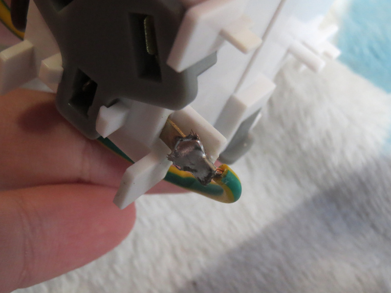
- Earth.JPG (125.16 KiB) Viewed 215734 times
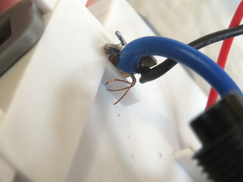
A few of the wire strands were pushed aside where inserted through the neutral and earth tags, although the connections remain good enough to survive 15A without scorching heat (see below).
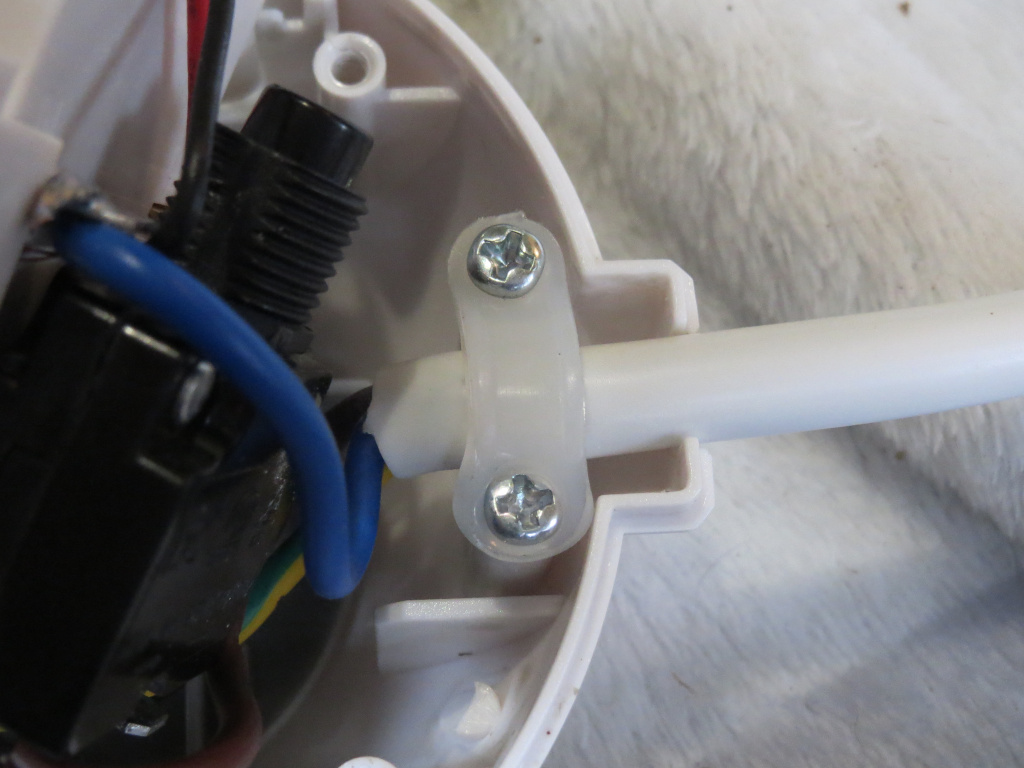
- Clamp.JPG (202.25 KiB) Viewed 215734 times
One of the cord clamp's screws has pressed into the clamp, although it still holds onto the cord; at least nothing's outright broken here.
I added washers under the screw heads (as you can see in the above pictures) to salvage it.
No surge-suppressor is included (nor claimed), but I prefer this to having MOV(s) with no failsafe (especially in a plastic housing).
USB supply
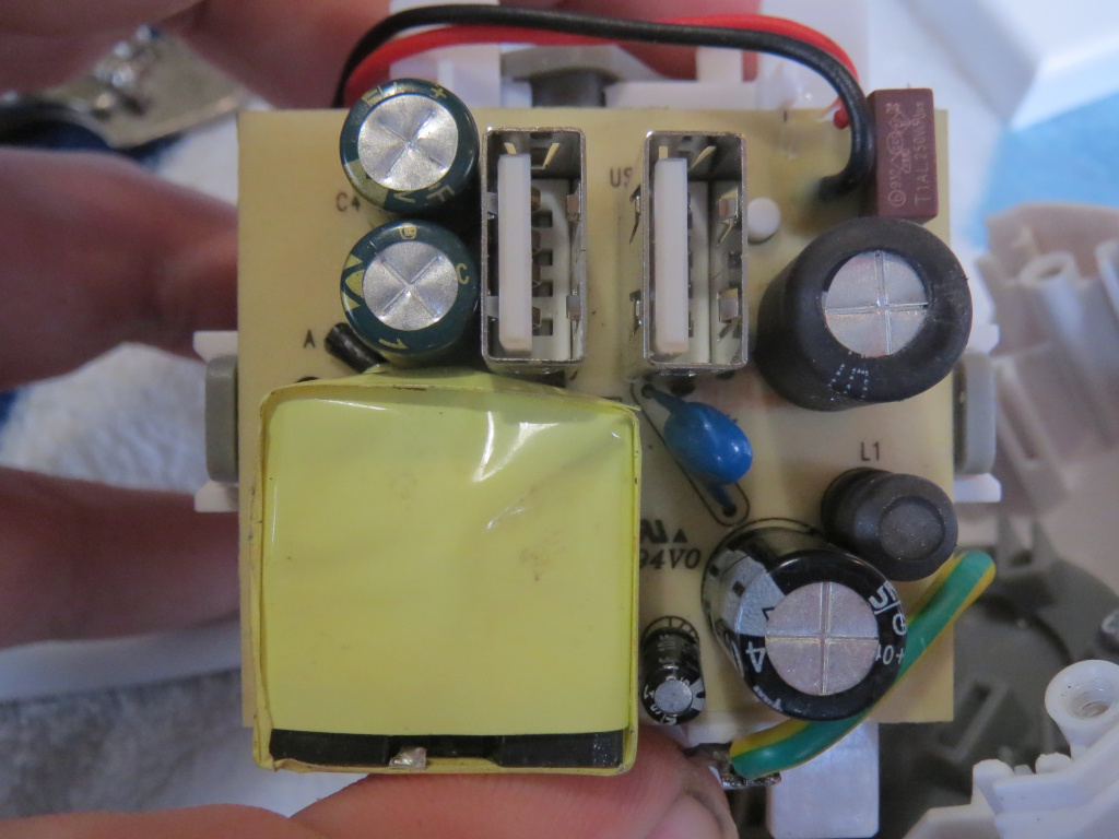
- USB-front.JPG (247.85 KiB) Viewed 215734 times
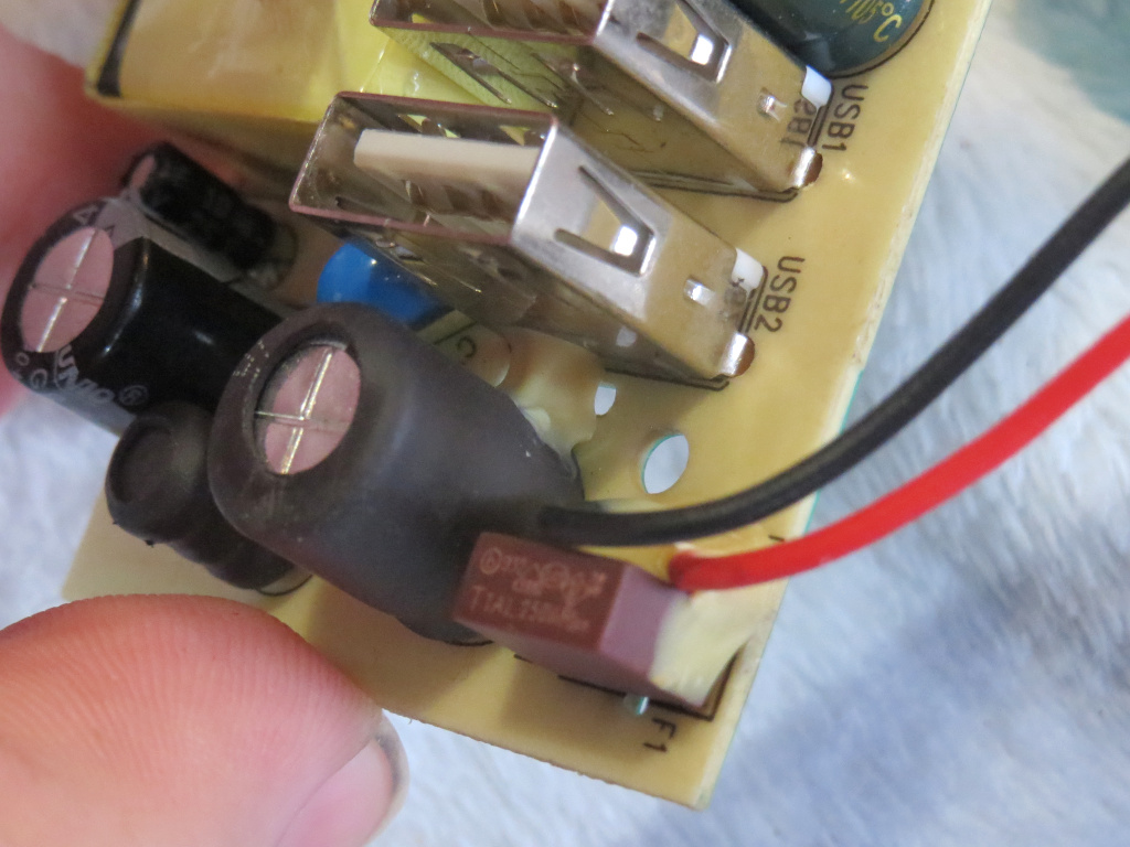
- Glue.JPG (246.82 KiB) Viewed 215734 times
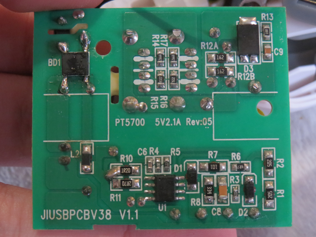
- USB-back.JPG (294.33 KiB) Viewed 215734 times
Unsurprisingly, this is the weakest part; on top of questionable capacitors, this one also has the bad glue (the PowerCube used silicone here). (Neither piece I see is on or next to a major heat source, but still.) The single-insulated mains wires (
UL AWM 1007, 24AWG) are also run somewhat close to the secondary components; some heatshrink there would have been appropriate. It does have a proper fuse (T1A 250V) rather than a fusible resistor, though.
The output capacitors are 2×1000μF 10V 8mm Qunio TM series, rated for 576mA ripple each (although these are slightly shorter than specified); this isn't entirely adequate for a 2.1A flyback converter, especially with the hot rectifier diode (SVM1045V) right on the back of the PCB.
The primary capacitors are 2×10μF 400V 10mm Qunio GR and a 10μF 25V 4mm one is on Vcc for the FT839ND1.
The cramped design provides no room for these to vent, so who knows what can happen then…
There is also some flux residue around BD1 (ABS10), and a solder chunk stuck to the transformer tape.
Load testingNow that I've
modified an MPT-301 to provide current limiting (with a potentiometer adjusting the threshold), I can load the mains outlets with much more accurate current control than by powering heaters through it (and also without wasting electricity, and opening windows or cranking up the A/C, in summer

).
10A load through the active and neutral paths went fine, overloading to 20A tripped the breaker in 4 to 5 seconds. However, there's an additional test we can try:
Passing current neutral-to-earth (to bypass the breaker), so I can overload it in a controlled manner. I believe IEC 60320 (though I haven't seen it firsthand so don't quote me on that

) requires its connectors to survive a 25% overload (12.5A in this case), so I tried that; 2 hours later and it isn't even unduly warm.
Up to 15A for an hour; noticeably warm, but still holding together. (I'm using a rewireable Clipsal plug in the sockets here; molded plugs often get much hotter due to weak connections, especially after repeated strain.)
As for the USB supply, I have five 5.1Ω 5W resistors to hand, so have paralleled two of them with three 100Ω. Measured voltage at the end of the USB cable I used falls to about +4.7V (so about 2A actual), and the nameplate gets quite warm. It seems to work, but as made, I don't trust it long-term. The ripple is pretty bad too, over 150mV at room temperature (slightly lower once warmed up); a poly-mod gets it
barely within the equivalent of ATX specification.
ConclusionThe outlet block is somewhat better-made than Allocacoc's, while the USB supply is of about the same quality (middling at best).
So I can recommend the non-USB version (a first for any modern power-board or equivalent!), but will have to leave this USB one with:

- HM-200px.png (16.21 KiB) Viewed 215734 times
Still, I was able to recap it (with polys on the output, Rubycon AX on the input) and remove the glue; and also ran an earth wire to the USB output (given my standpoint that any SMPS powerful enough to require Y capacitors should really be Class I).
Next up are some fixed-installation electrical accessories from a small Australian company; will Clipsal be credibly threatened, or remain as royalty?
UPDATE: Non-USB model (PT5711)I bought three of these online (from DSE since OfficeWorks, the only other reasonably-priced seller, was down to only one in stock).
The end socket, unlike in Allocacoc PowerCubes, is its own unit connected to the main block by wires:
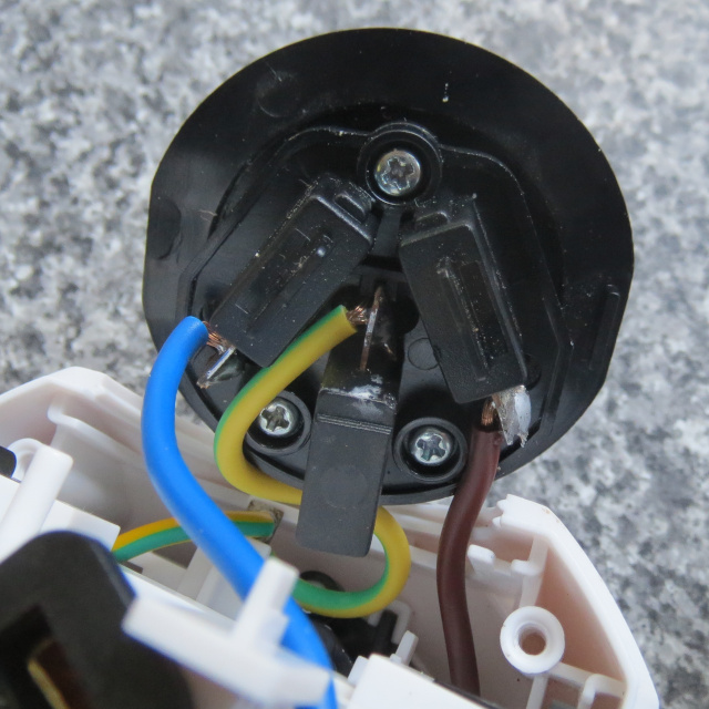
- End socket rear.JPG (162.52 KiB) Viewed 214572 times
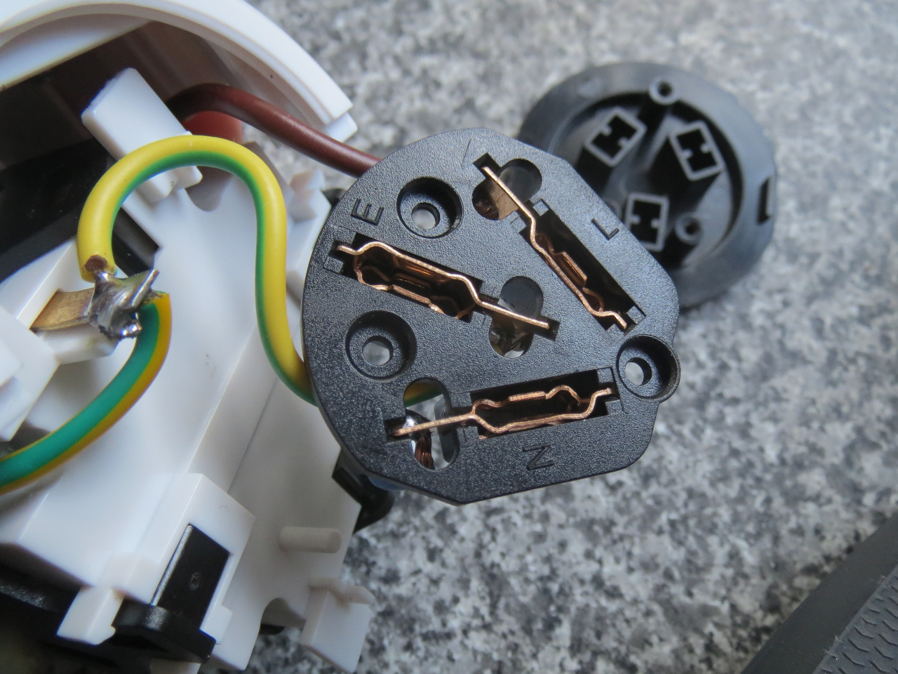
- End socket open.JPG (452.23 KiB) Viewed 214572 times
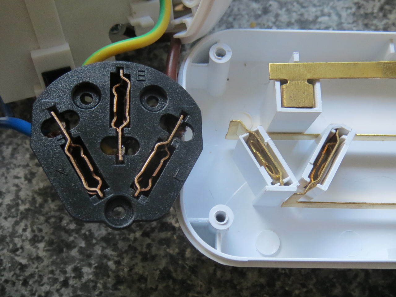
- Versus Crest PWA04984
- Contact comparison.JPG (411.52 KiB) Viewed 214572 times
The contacts here are somewhat similar to the conventional type, although made of phosphor-bronze and with curved sections for a bit more spring.
Many (though by no means all) of Jackson's regular power-boards have the same arrangement of curved sections in their active and neutral contacts, although in brass (you may be able to see it through the packaging if held up to light at the right angle).
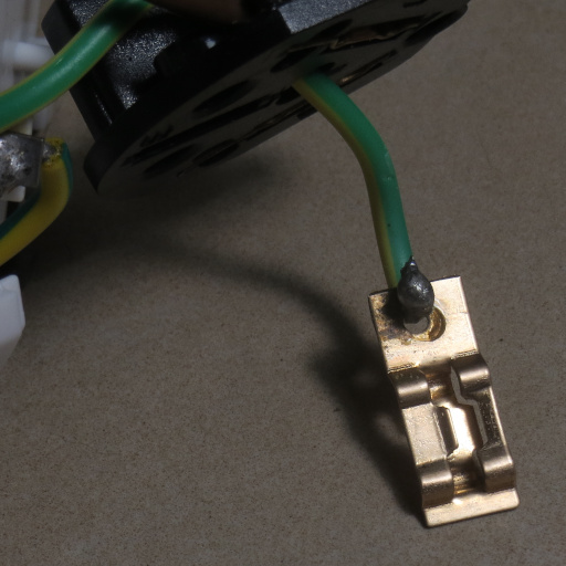
- Bad joint.JPG (96.55 KiB) Viewed 214572 times
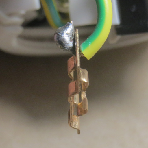
- End-on.JPG (78.02 KiB) Viewed 214572 times
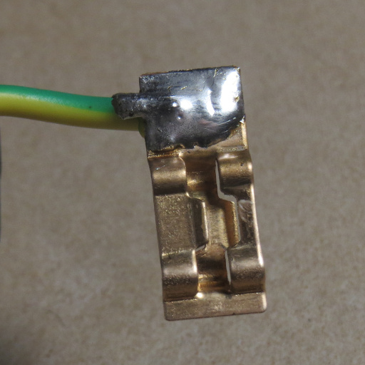
- Resoldered.JPG (93.03 KiB) Viewed 214572 times
Unfortunately, one unit had a failed solder joint on the earth connection (which is a bit cramped to reach in-situ) so I had to resolder it.
Circuit breakers tripped in 28, 32 and 40 seconds with a precise 20A. The cord clamps appear to be a slightly-whiter plastic and no screws have pressed into the hole. All casing screws are 10mm long, and the provided base mounting screws are also a bit different (with some added texture on the head).
Since these are still as good as ready-made options get in Australia now, my recommendation
just holds. But if you want to build something
really solid…
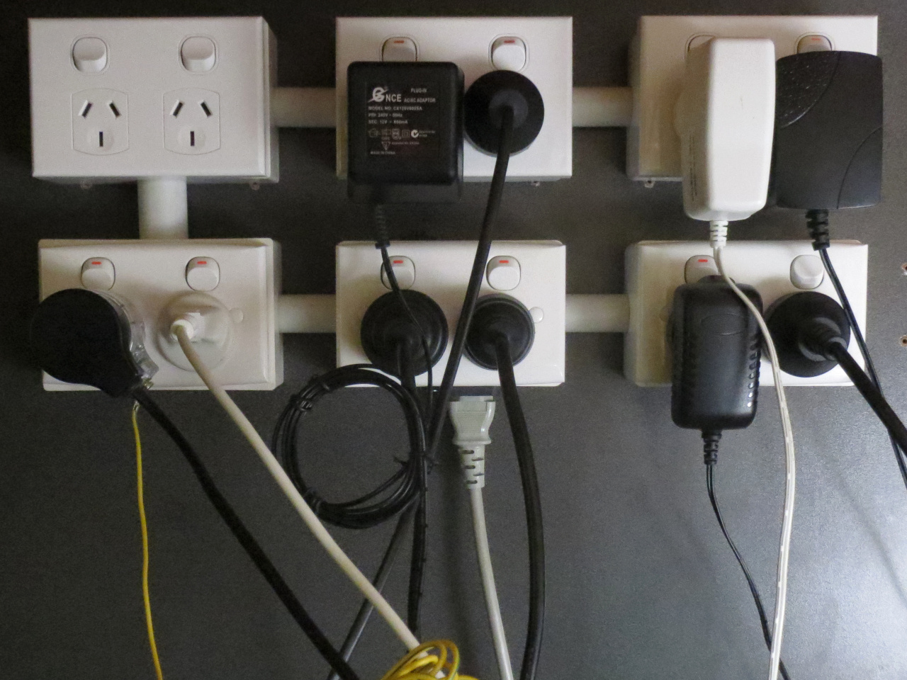
- Top: (2 empty), headphone amplifier, camera battery charger, external HDD, internet gateway. Bottom: Anti‑static point (via Clipsal 463SAS) + Stylux T‑869 (with 4W 4000K LED), heating pad (Sunbeam EP5000), monitor (Dell U2713HM), PC, desk lamp (TaoTronics TT‑DL22), printer (Kyocera P2040dn)
- Desk-back power outlets.JPG (411.58 KiB) Viewed 214572 times
…you can follow the lead of
1970s Kambrook: Buy enough twin outlets for the purpose, along with the same number of back boxes (with conduit ports where needed), some conduit for wire protection between the boxes, at least 3m of cable (I used 1.5mm² 7-strand TPS, but probably flexible with ferrules for any future rewiring), a 10A thermal circuit breaker (which I salvaged from a cheap UPS) and C14 inlet. If I had a 3D printer I'd design a frame enclosing the mounting nuts for the IEC inlet, but I don't so I've instead formed plastic sheets (salvaged from PSUs) to provide barriers between the wiring and screws/nuts; otherwise you could use nylon screws (which I did in an earlier iteration), or possibly make an earthed metal plate to put under the nuts (with star washers in-between).
If not mounting it to an existing structure, you'll also have to fashion your own baseboard.
 Not yet sure of the exact deficiency, but it would have been perfectly easy to ground the metal base for a bottom shield (and I can't imagine a suitable top shield adding much more cost either).
 , with no shielding. (It does otherwise work, but clearly not worth the AU$12.95)
 ) modern power-boards I've seen so far (surprisingly available at Coles), with reasonably sturdy casings and socket contacts of ordinary design but clean brass; the PWA04984 has 4 sockets, while PWA04985 has 6 sockets and a master switch (which is actually double-pole although not stated as such); otherwise they're much the same, and on both models the left-most socket has a wider spacing (55mm) than the rest (45mm). Both contain a single 14mm MOV (claimed to absorb 175J suggesting a nominal 470V or thereabouts) from active to neutral, protected by an adjacent thermal fuse plus F3.15A HRC fuse (although with the usual arrangement where the load remains on); the indicators are green InGaN LEDs driven half-wave through 3MΩ resistors, so heating there is negligible (and they are in opposite polarities to cancel out the DC component, however small it is, for as long as the MOV remains enabled). The cord (standard H05VV-F3G1.0 with a side-entry plug, manufactured by Conghao) measures accurate to the stated 1.2m, and at 20A the circuit breaker trips in about 15 seconds.
 ); these include the PWC4100 (4-socket master switched), PWC4400 (4-socket individually switched), PWC4402 (the same + 2 USB) and PWC6100 (6-socket master switched), none of which claim any surge suppression (although all have the same wide-spaced socket on the left). Will add those to this thread if I get one (or more)…
 ) heating elements (also NiCr rather than FeCrAl) for fast toasting (although somewhat uneven, due to some parts expanding away from the mica and therefore glowing hotter; but nearly all conventional toasters suffer this to some extent).

 ).
).

 .
. ) requires its connectors to survive a 25% overload (12.5A in this case), so I tried that; 2 hours later and it isn't even unduly warm.