Contents
- 1Introducing the Corsair CX550M
- 1.1Packaging and accessories
- 2Connectors & cabling
- 2.1Casing & cooling
- 3Input filtering
- 4Primary side
- 4.1+5 V stand-by rail
- 5Secondary side
- 5.1Build quality
- 6Load testing
- 6.1Loading +5 V SB
- 6.2Voltage hold-up time
- 6.3Combined loading
- 6.4Combined loading ripple
- 6.5Crossloading, overloading
- 6.6Crossloading, overloading ripple
- 6.7Fan speed, temperatures and noise
- 7Conclusion and evaluation
- 7.1Bonus
- 7.2Thanks
- 7.3Discussion
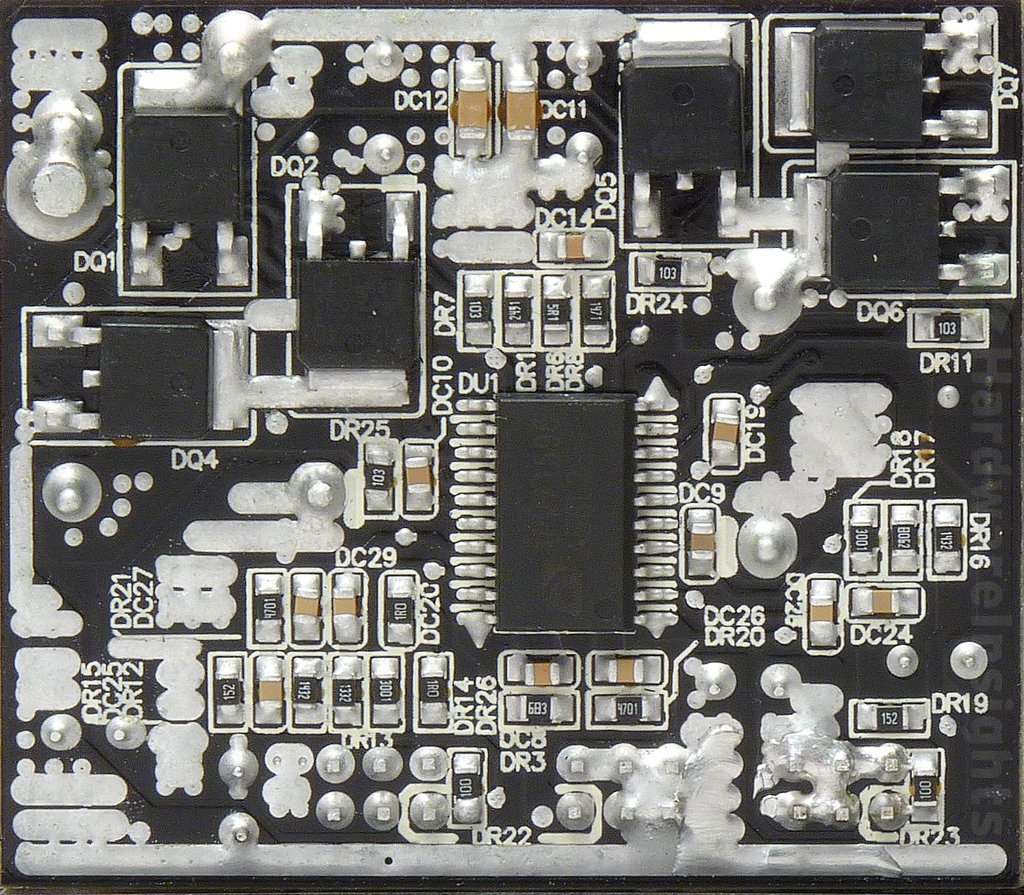
Secondary side
The secondary synchronous rectification handles this “S650-SR+FAN CARD”, which is a daughterboard you can see just behind the transformer. It carries SP6019 synchronous rectifier driver which drives 2×2 transistors. Those are Infineon BSC039N06NS (100/400 A at 60 V, RDS(On) 5.9 mΩ at 30 A and VGS of 4.5 V, 3.9 mΩ at 10 V) in a PG-TDSON-8 package. There is no extra cooling for them other than four copper strips which also serve to conduct the currents to the main board. There is a copper foil (insulated by plastic) between the board and the large inductor for EMI shielding.
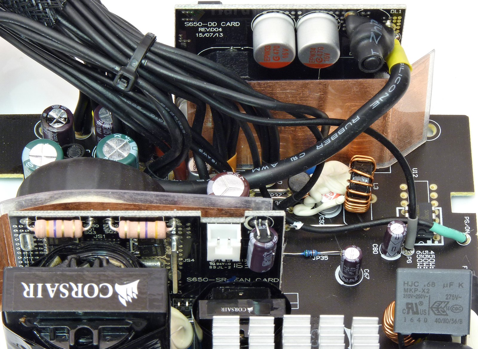
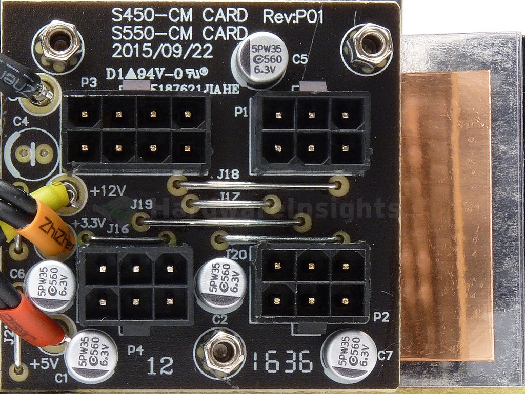
The filtering consists of two Samxon GF 2200/16 and two Su’scon 1000/16 capacitors. There are also two Apaq AREP 470/16 polymers on the input of the DC–DC board. The transistors on the board are Ubiq Semiconductor QM3006D (80/160 A, 30 V, 5.5 mΩ@10 V/30 A, 9 mΩ@4.5 V/15 A) for +5 V and QM3004D (55/110 A, 30 V, 8.5/14 mΩ) for +3.3 V. The controller is the Anpec APW7159C. For the output filtering there are two AREC 820/6.3 polymers on the module and also one more AR5P 560/6.3 on the main board. For the −12V rail CWT used the Anpec A5268 buck regulator and two AREA 100/16 polymers. There is another copper sheet located behind the board.
A few dual-16AWG wires conduct power to the small modular board. Three more AR5P 560/6.3 polymers help filter the +5 V rail, while two filter the +3.3 V directly on this board.
The fan controller circuit is combined on to the rectification board and also present is an LM393 dual comparator for this purpose. I found at least one SMD thermistor on the board to sense the temperature. For the secondary monitoring, the CX550M has a Weltrend WT7502 microchip which only monitors the basic set of functions (UVP, OVP, SCP) and signals (Power Good, PWR On). There are vacant spots for a full-sized 14pin supervisor IC and its complimentary circuit though.
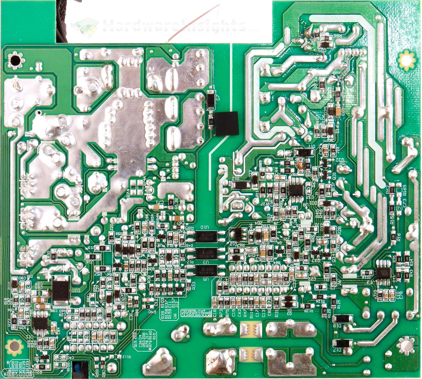
Build quality
As usual, I’ll focus on the overall build quality and other things like electrical safety here, as the quality of the components that were used was already discussed before. The separation between the primary and secondary sides is good. You can notice a rubber pad which helps support the weight of the board. The soldering is mostly good though there are joints which do not seem adequate (or perhaps more than just a ‘few’ of them). Seems to me this CWT assembly line is rushing things a bit. The overall work is mostly clean but I found a couple of manually-resoldered joints which have not been cleaned afterwards, specifically around one of the primary switchers. It is not really that good of an idea to have that amount of residue present around a high-voltage switcher.
The modular board is somewhat dirty with soldering flux residue, but fortunately there are only low voltages present on it so it does not matter that much. Quite a few of the component leads could have been trimmed shorter. Overall, the design is nice and clean though some of the components are virtually covered by silicone. The board is from Jia He Electronic Ltd. and the component side is quite nice. It appears to me that it consists of a layer of totally different material (some nice plastic) bonded on top of the underlying ones. I would say that the overall manufacturing quality is OK for the mainstream, but the soldering could be a little better. For me, it is minus three points here.