Contents
- 1Introducing the Corsair CX550M
- 1.1Packaging and accessories
- 2Connectors & cabling
- 2.1Casing & cooling
- 3Input filtering
- 4Primary side
- 4.1+5 V stand-by rail
- 5Secondary side
- 5.1Build quality
- 6Load testing
- 6.1Loading +5 V SB
- 6.2Voltage hold-up time
- 6.3Combined loading
- 6.4Combined loading ripple
- 6.5Crossloading, overloading
- 6.6Crossloading, overloading ripple
- 6.7Fan speed, temperatures and noise
- 7Conclusion and evaluation
- 7.1Bonus
- 7.2Thanks
- 7.3Discussion
Load testing
Loading +5 V SB
As always, all load testing is done according to our testing methodology. The voltage regulation is nice for a mainstream unit, it stays within 1 %. The ripple is nice and the efficiency is also great at over 76 %, I think that’s worth a point for a mainstream unit.
| Output (W) | Load (A) | Voltage (V)/ ripple (mV) | Input (W) | Efficiency/power factor |
| 0 | 0 | 5.030/5.800 | 0 | —/0 |
| 14.51 | 2.91 | 4.987/6.200 | 19.03 | 76.3 %/0.424 |
| 17.03 | 3.42 | 4.980/5.200 | 22.23 | 76.6 %/0.453 |
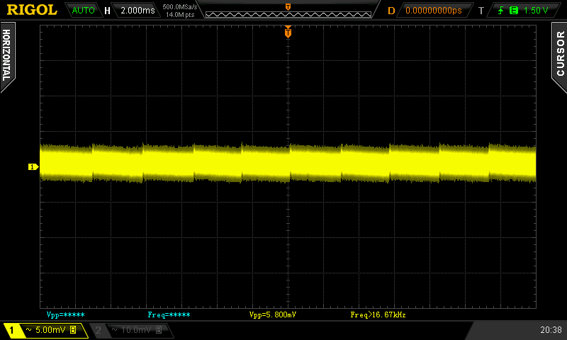
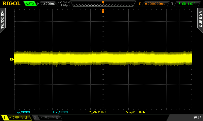

+5 V SB ripple (left to right): 0 A; 2.91 A; 3.42 A
Voltage hold-up time
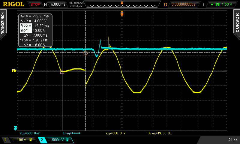
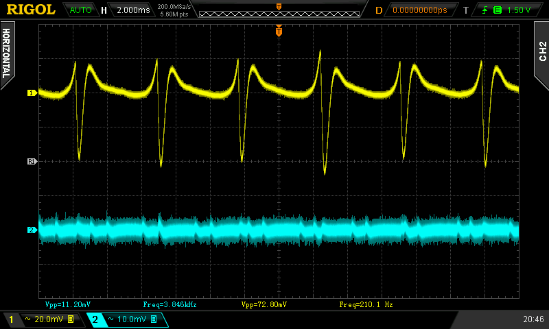
As we can see on the oscilloscope screenshot, the hold-up time of the +12 V rail is very short at only 11.20 ms. This is definitely a direct result of such a low rated input capacitor. I have been told that the hold-up time is designed to be “over 10 ms” so this would be consistent.
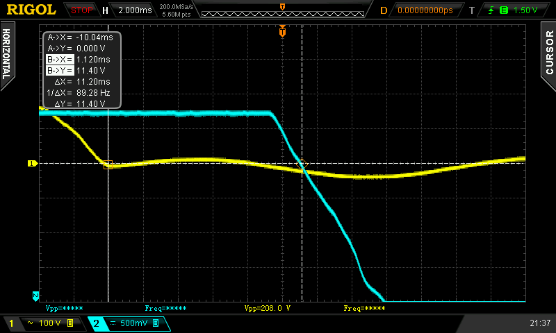
The power good signal hold-up time is even shorter though at only 8.360 ms which does not even make it to my minimum of 10 ms nor to Corsair’s minimum of 10 ms. The problem however may lie in a simple misunderstanding somewhere between me, Corsair and CWT. As there are actually two different hold-up time figures (voltage – for different rails – and PWR Good signal), it may be just that they tested voltage HUT only, which is in their spec, as shown above, but not PWR Good. With this hold-up time being so short, not even a UPS (neither a cheap/off-line model, nor an older one with worn out relays) may help you under full load, as its own transfer time may be longer than this. I have no other choice then but to declare that the Corsair CX550M fails to meet the ATX specification here, not to mention my own, more lenient 10 ms requirement.
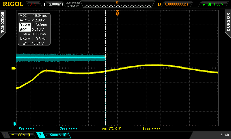
Interrupting the AC input exactly for 8.3 ms revealed that the voltage continued to drop for a while before the unit kicked back in. So I had to decrease the time further down to about 7.800 ms when only then it was kept within spec. Honestly, this is just way too low. This unit needs a 270μF bulk capacitor at the very least, but 330+ would be an even better option. Even if they would have just put a higher-rated Teapo or even a C(r)apXon in there, but with a 420V rating to match the endurance of a Japanese capacitor, it would have been preferable over a quality Japanese cap, but one which utterly causes the unit to fail to meet spec.
Combined loading
Combined loading was OK for the Corsair CX550M. Firstly, let’s talk about the voltage regulation. The results are very good for the price, I’d say almost unnecessarily too good. Corsair could have kept the inferior regulation, but rather have used the saved money for a proper bulk capacitor. Everything stays within 2 %, and even the load regulation of the stand-by rail is just 2.2 %. These are practically high-end figures.
| Output power | Load/ voltage +5 V SB | Load/ voltage +3.3 V | Load/ voltage +5 V | Load/ voltage +12 V | Load/ voltage −12 V | Input power | Efficiency/ power factor |
| 5.4 %/ 29.86 W | 0 A/ 5.023 V | 0 A/ 3.310 V | 0.414 A/ 5.065 V | 1.864 A/ 12.209 V | 0.407 A/ −12.323 V | 42.91 W | 69.6 %/ 0.751 |
| 20 %/ 118.81 W | 0.532 A/ 5.003 V | 2.85 A/ 3.310 V | 1.600 A/ 5.063 V | 7.68 A/ 12.191 V | 0.404 A/ −12.342 V | 139.7 W | 85.0 %/ 0.943 |
| 40 %/ 221.82 W | 1.021 A/ 4.985 V | 4.07 A/ 3.312 V | 2.31 A/ 5.062 V | 15.33 A/ 12.170 V | 0.406 A/ −12.353 V | 253.7 W | 87.4 %/ 0.977 |
| 60 %/ 334.48 W | 1.88 A/ 4.958 V | 5.48 A/ 3.313 V | 4.96 A/ 5.054 V | 22.8 A/ 12.147 V | 0.405 A/ −12.373 V | 382.8 W | 87.4 %/ 0.988 |
| 80 %/ 434.56 W | 2.37 A/ 4.935 V | 7.02 A/ 3.315 V | 6.12 A/ 5.053 V | 30.0 A/ 12.122 V | 0.406 A/ −12.395 V | 502.8 W | 86.4 %/ 0.990 |
| 100 %/ 551.62 W | 2.82 A/ 4.913 V | 8.38 A/ 3.317 V | 6.79 A/ 5.054 V | 38.9 A/ 12.098 V | 0.407 A/ −12.404 V | 651.0 W | 84.7 %/ 0.994 |
As for the overall efficiency, it reached over 87 % on my equipment and on average 86.2 %. This is well above 80 PLUS Bronze, I think that this platform may be easily made 80 PLUS Silver next time.
Combined loading ripple
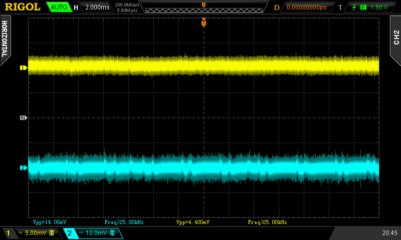
The ripple values start out exceptionally well, but later on, starting at about 80% load, there is a dramatic increase and though it still keeps it in spec, the stand-by supply exceeds my personal limit for mainstream units. I am curious if this is also because of the small input bulk cap which then causes the transistors to switch more. The −12V rail also has some serious trouble keeping up with the fan-induced ripple.
| Output % | Ripple +5 V SB | Ripple +3.3 V | Ripple +5 V | Ripple +12 V | Ripple −12 V |
| 5.4 | 6.000 mV | 4.400 mV | 5.600 mV | 16.00 mV | 72.80 mV |
| 20 | 5.400 mV | 4.000 mV | 6.200 mV | 14.00 mV | 75.20 mV |
| 40 | 8.000 mV | 5.600 mV | 5.800 mV | 13.80 mV | 72.00 mV |
| 60 | 6.200 mV | 7.000 mV | 8.600 mV | 14.60 mV | 76.80 mV |
| 80 | 33.20 mV | 18.80 mV | 19.60 mV | 53.60 mV | 86.00 mV |
| 100 | 38.40 mV | 20.00 mV | 31.20 mV | 59.20 mV | 96.00 mV |
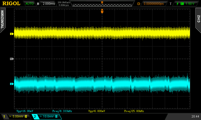
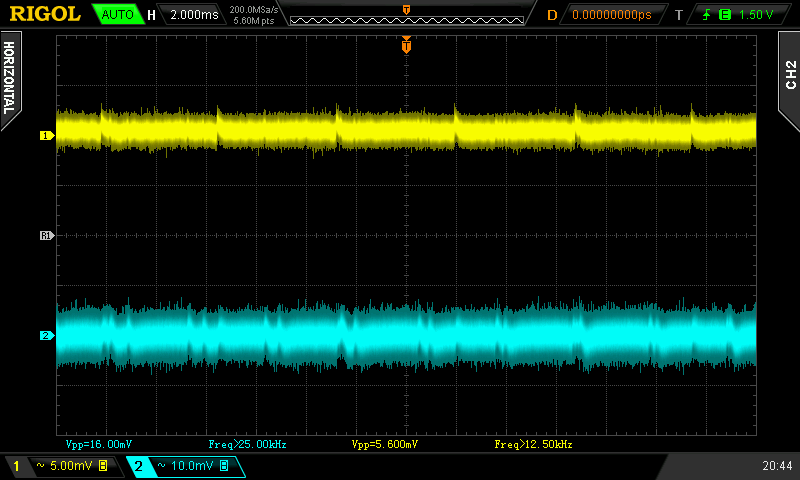
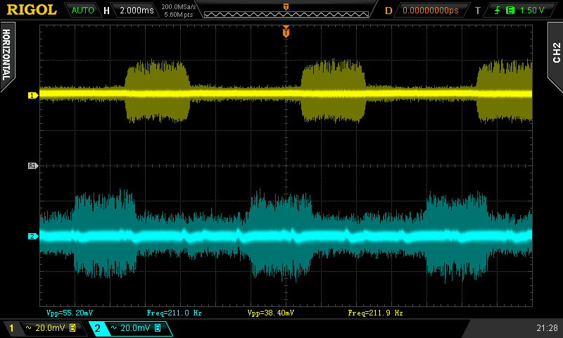
Ripple 5.4% load (left to right): +5 V SB; +3.3 V; +5 V; −12 V. The second channel is connected to +12 V.
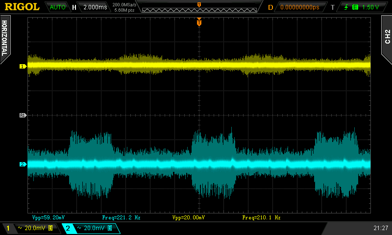
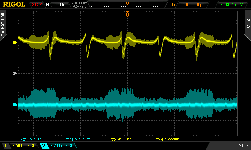
Ripple 100% load (left to right): +5 V SB; +3.3 V; +5 V; −12 V. The second channel is connected to +12 V.
Crossloading, overloading
Crossloading tests were also fine, as could be expected from a platform that uses DC–DC modules. The regulation was mostly the same so there is very little to say. Efficiency is also reasonable. I barely managed to load the +3.3V rail to its maximum rated output but the +5 V did not react to a maximum applied power draw. It is possible that the OCP is functioning there, but the specified limit is much higher.
| Output power | Load/ voltage +5 V SB | Load/ voltage +3.3 V | Load/ voltage +5 V | Load/ voltage +12 V | Load/ voltage −12 V | Input power | Efficiency/ power factor |
| 21 %/ 116.05 W | 0.527 A/ 4.986 V | 23.5 A/ 3.307 V | 1.618 A/ 5.060 V | 1.857 A/ 12.188 V | 0.408 A/ −12.402 V | 150.5 W | 77.1 %/ 0.950 |
| 25 %/ 134.83 W | 0.523 A/ 4.990 V | 1.450 A/ 3.311 | 19.84 A/ 5.023 V | 1.867 A/ 12.190 V | 0.404 A/ −12.387 V | 164.5 W | 82.0 %/ 0.956 |
| 98 %/ 538.53 W | 0.515 A/ 4.955 V | 1.445 A/ 3.322 V | 1.583 A/ 5.071 V | 42.8 A/ 12.104 V | 0.412 A/ −12.387 V | 628.3 W | 85.7 %/ 0.991 |
| 119 %/ 657.13 W | 3.315 A/ 4.903 V | 1.455 A/ 3.316 V | 2.309 A/ 5.065 V | 54.1 A/ 11.444 V | 0.423 A/ −12.390 V | 778.3 W | 84.4 %/ 0.996 |
Unfortunately combined overload tests showed the usual behaviour. The OPP does not seem to work, and there’s only a power limit from the primary side which resulted in the +12V rail voltage going down the toilet after reaching approx. 650 watts. Applying a faster transistor load made no difference, the OCP just did not trigger, if there even is any present at all. The unit shut down after the voltage fell to under 9.6 V. This is a quite poor UVP implementation as well.
Crossloading, overloading ripple
The ripple values were equally good at the beginning and equally bad at the end.
| Output % | Ripple +5 V SB | Ripple +3.3 V | Ripple +5 V | Ripple +12 V | Ripple −12 V |
| 21 | 5.400 mV | 4.600 mV | 6.000 mV | 10.60 mV | 71.20 mV |
| 25 | 7.400 mV | 5.400 mV | 7.800 mV | 11.20 mV | 72.80 mV |
| 98 | 35.20 mV | 13.20 mV | 36.00 mV | 44.00 mV | 88.00 mV |
| 119 | — | — | 44.00 mV | 64.00 mV | — |
Fan speed, temperatures and noise
The fan of the CX550M started spinning right away, but until test six (100 % load) it stayed at just about 900 RPM, and at that speed it was audible (at 38.8 dBA ambient), but very quiet. At full load, the speed increased significantly and it got slightly more audible but was still reasonable. At full speed under overload the fan was noisy.
| Output % | Fan speed (RPM) | Temperature intake/ outtake | Noise (dBA) |
| 5.4 | 887 | 22 °C/ 24 °C | 39.0 |
| 20 | 898 | 23 °C/ 27 °C | 39.0 |
| 40 | 905 | 23 °C/ 31 °C | 39.0 |
| 60 | 912 | 23 °C/ 34 °C | 39.0 |
| 80 | 923 | 24 °C/ 38 °C | 39.0 |
| 100 | 1480 | 25 °C/ 42 °C | 40.1 |
| CL 21 | 899 | 22 °C/ 32 °C | 39.0 |
| CL 25 | 904 | 22 °C/ 31 °C | 39.0 |
| CL 98 | 1473 | 25 °C/ 39 °C | 40.1 |
| OL 119 | 1940 | 24 °C/ 44 °C | 43.9 |
The temperatures were higher than I would have expected them to be. As the rectification module has pretty much no heatsink area, as I found later during modification, it gets quite warm. But the transformer and the 12V inductor are really hot. Combine this heat with those known bad Samxon GF series capacitors, and all I can say is that that may not have been an overall wise design decision on their part.