Contents
Closer specification and repair itself
The power board is screwed using three screws. The cable from it, leading to signal board, is hard-soldered into the power board and can only be disconnected from the signal board. If you have some practice, you can unplug it directly, but plugging it back is tricky. If you have difficulty, then also remove signal board, connect the cable and place it back. For that you need to remove hexagonal screws by the sides of the D-Sub connector. I personally try to avoid this extra work.
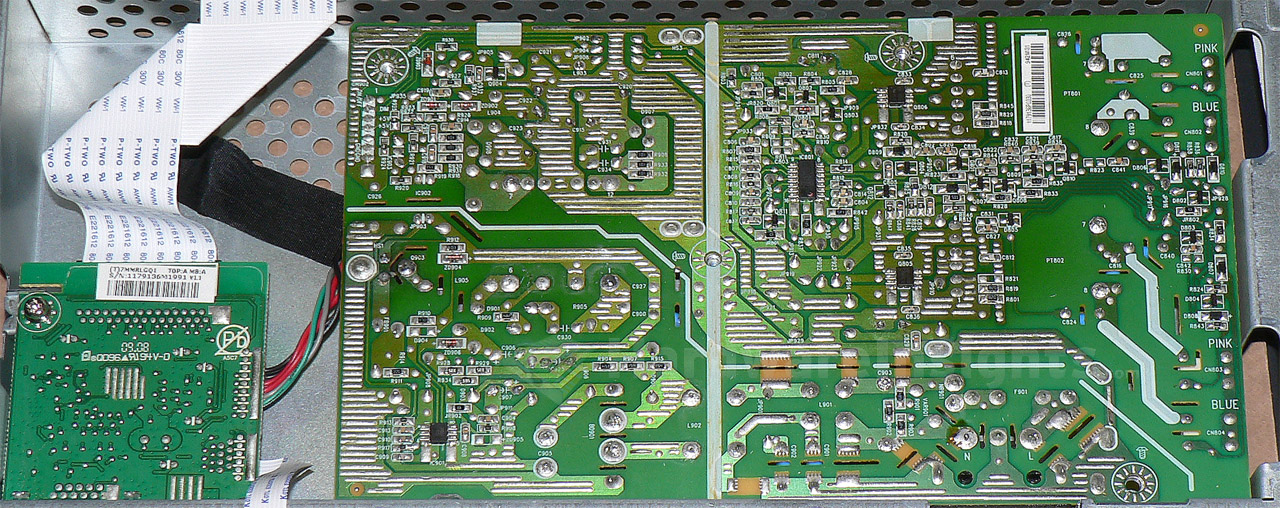
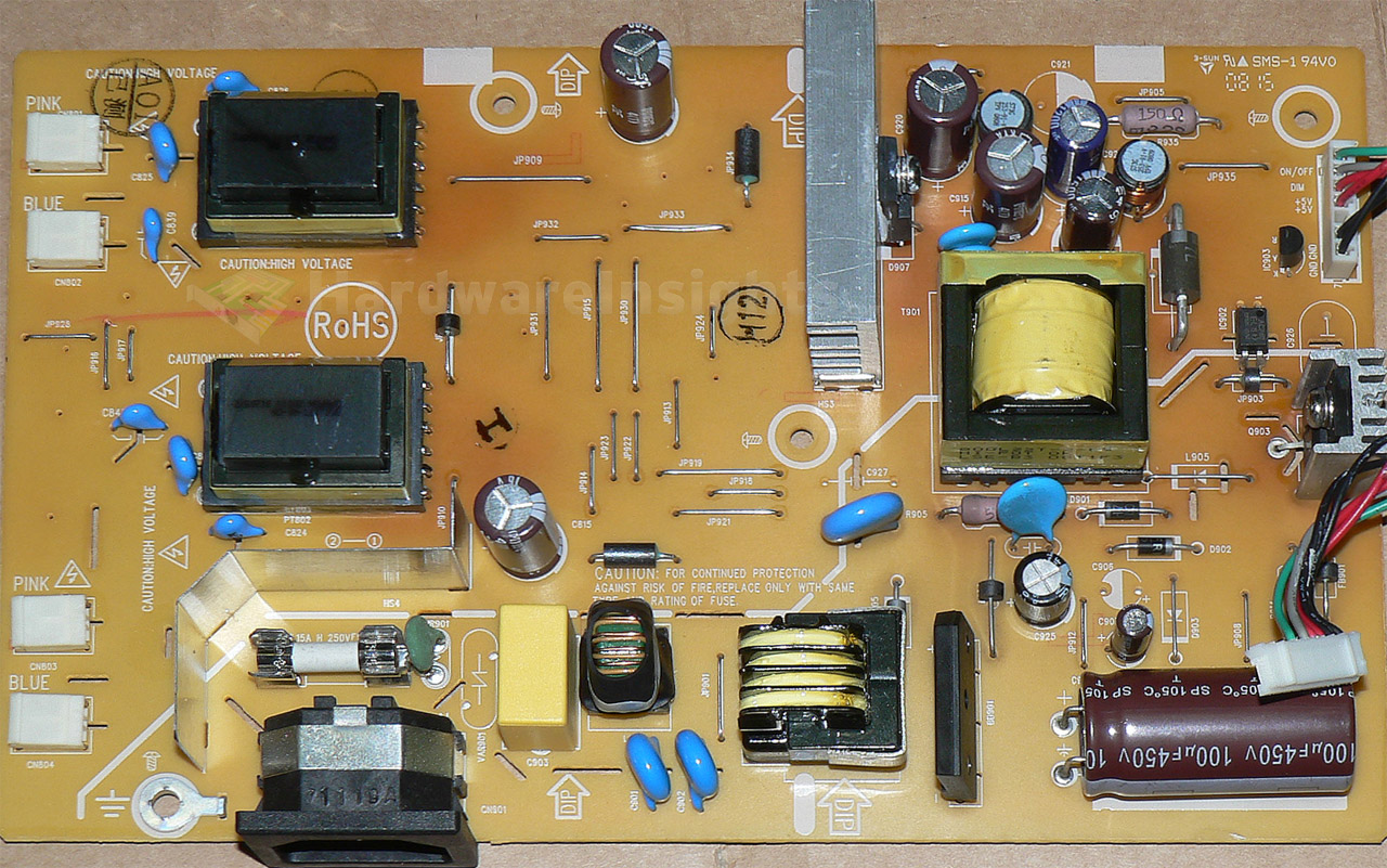
The power supply board including the inverter is a typical board of AOC origin, model 715G2905-1. It has +5V stand-by rail and main +14.5V rail for inverter. At first glance, no problem here. The capacitors seem fine and nothing looks blown. The transformers also measure fine (their secondary winding resistance must not differ by more than 2-3 %). Not even output rectifiers or inverter transistors appear to be shorted. This will not be usual output problem. AOC lately uses Hermei capacitors (especially in ASUS displays), I do not trust this brand even though I have not yet seen any go bad. Yet.
The soldering also appears intact, although there is some heat discolouration visible on the PCB.
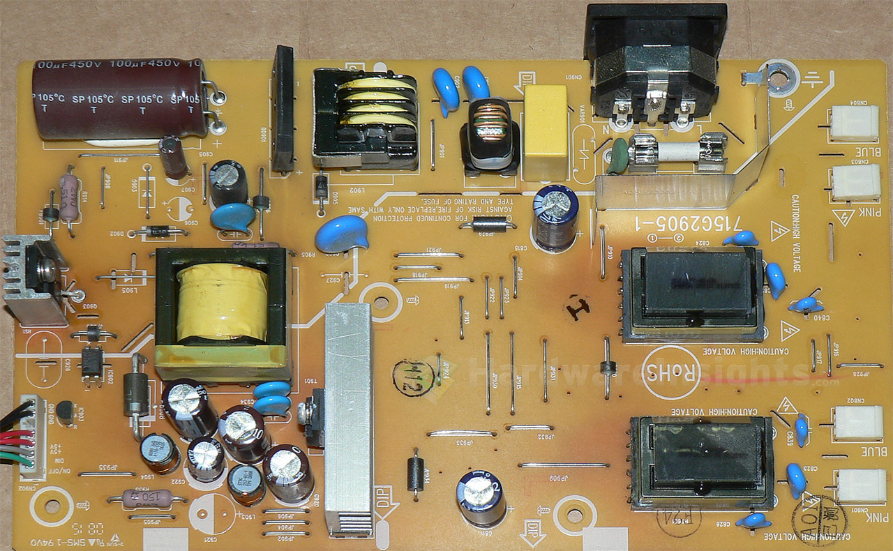
Well well, what have we got here? This transistor seems to be baking itself a bit (note the discolouration on the PCB immediately around it). Some excessive switching? That regularly rapid-blinking LED fed from standby rail also points to a suspect…

And here it is, a failed Hermei cap! I was right once again by replacing them immediately. Replace on sight! They used this strange byroad from not-yet rectified AC voltage just before the input rectifier, with separate diode for half-wave rectification and separate 1μF (400V) capacitor, which is under continuous stress of high ripple current and of course will go bad after time. There is absolutely no reason not to get that rectified and smoothed 325 V DC directly from the big input capacitor and just lower the voltage with some resistors.
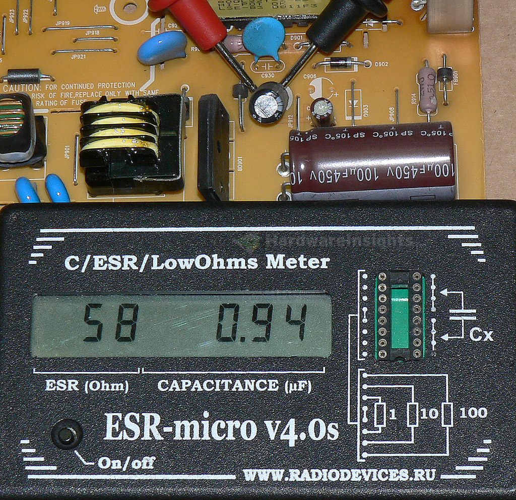
If this is not done on purpose, then the designer of this thing is complete idiot. Then somebody is going to tell me that nooo, things are not intentionally designed to break. Yeah sure. By the way, without ESR meter, you will not be able to find this problem. The capacitor looks just fine and the capacitance was well within tolerance, yet the ESR went through roof. This capacitor is not filtering at all, thus the driving IC gets high ripple voltage feed and that makes it work only for a fraction of each second, resulting in such oscillations, which were only capable of feeding that small LED.
If you will need, I can supply you with new generation of ESR Micro v4.0si including full relay protection from charged capacitors with discharge circuit. For a good price of course. On the picture is mine older generation v4.0s, now available with discount.
The capacitor in question has been replaced with an older used Nichicon which was in hand. At the moment, I do not stock such capacitors, but I have brand new line of Rubycon capacitors being manufactured, designed specifically for CCFL and LED lights, which are getting strong attention now. But because of the price, this monitor originally came with junk Chinese capacitors. And because of their tiny dimensions (8mm diameter), they go bad even more often than usually, often not even surviving warranty. These caps of mine have a capacitance of 3.3 μF for 400 V, and D8×11.5 mm dimensions and, a minimum rated lifetime of 15000 hours at 105 °C. These should be available around May. The other capacitors were replaced with Chemi-Con KYA 1500µF 16V, KZN 1500µF 6.3V, LXZ 1200µF 6.3V and a small one which I do not remember exactly, everything is available from my stock for very good prices.

Well, we are finished here. One additional thing that may be added (even though not absolutely necessary), an MOV in the vacant spot, good for suppressing voltage spikes.
P. S.: another possible solution without any harm done is basically removing that capacitor nonsense with the single-way rectification and wiring a jumper wire from the big input capacitor’s anode to vacant anode spot of the small cap (being removed).